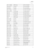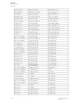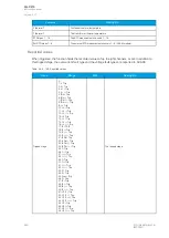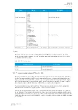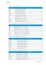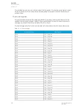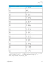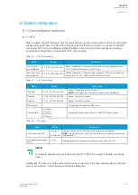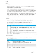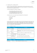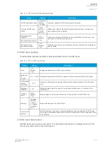
Name
Description
YLxSecMag
Admittance Y L1, L2, L3 secondary (mS)
YLxAngle
Admittance Y L1, L2, L3 angle (degrees)
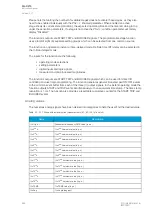
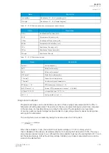
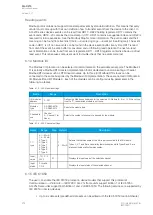
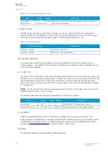
Table. 5.7 - 208. Other conductances, susceptances and admittances
Name
Description
G0Pri
Conductance G0 primary (mS)
B0Pri
Susceptance B0 primary (mS)
G0Sec
Conductance G0 secondary (mS)
B0Sec
Susceptance B0 secondary (mS)
Y0Pri
Admittance Y0 primary (mS)
Y0Sec
Admittance Y0 secondary (mS)
Y0Angle
Admittance Y0 angle
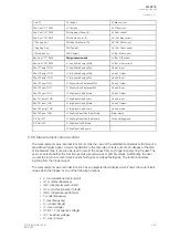
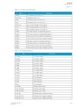
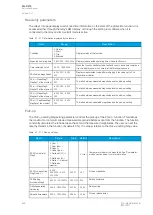
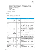
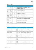
Table. 5.7 - 209. Other measurements
Name
Description
System f.
System frequency
Ref f1
Reference frequency 1
Ref f2
Reference frequency 2
M Thermal T
Motor thermal temperature
F Thermal T
Feeder thermal temperature
T Thermal T
Transformer thermal temperature
RTD meas 1…16
RTD measurement channels 1…16
Ext RTD meas 1…8
External RTD measurement channels 1…8 (ADAM)
mA input 7,8,15,16
mA input channels 7, 8, 15, 16
ASC 1…4
Analog scaled curves 1…4
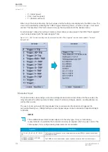
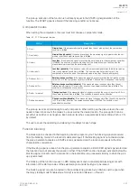
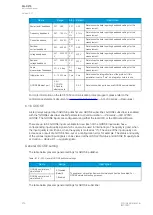
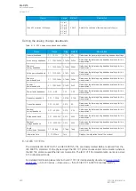
Magnitude multiplier
Programmable stages can be set to follow one, two or three analog measurements with the
PSx >/<
Measurement setting parameter. The user must choose a measurement signal value to be compared
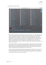
to the set value, and possibly also set a scaling for the signal. The image below is an example
of scaling: a primary neutral voltage has been scaled to a percentage value for easier handling when
setting up the comparator.
The scaling factor was calculated by taking the inverse value of a 20 kV system:
When this multiplier is in use, the full earth fault neutral voltage is 11 547 V primary which is
then multiplied with the above-calculated scaling factor, inversing the final result to 100%. This way a
pre-processed signal is easier to set, although it is also possible to just use the scaling factor of 1.0 and
set the desired pick-up limit as the primary voltage. Similarly, any chosen measurement value can be
scaled to the desired form.
A
AQ
Q-C215
-C215
Instruction manual
Version: 2.07
© Arcteq Relays Ltd
IM00040
265

