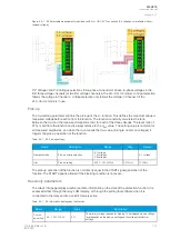
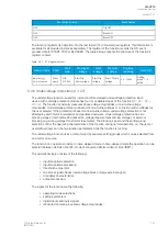
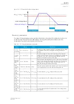


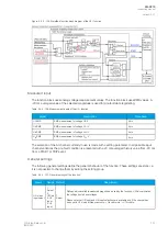

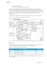
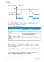
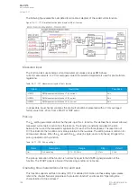

Figure. 5.4.9 - 108. Simplified function block diagram of the U0> function.
Measured input
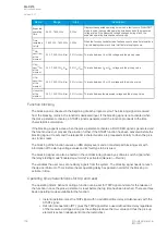
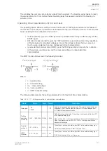
The function block uses analog voltage measurement values. The function block uses RMS values. A
-20 ms averaged value of the selected magnitude is used for pre-fault data registering.
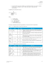
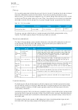
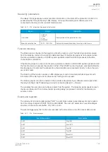
Table. 5.4.9 - 106. Measurement inputs of the U0> function.
Signal
Description
Time base
U0RMS
RMS measurement of voltage U0/V
5ms
U
L1
RMS
RMS measurement of voltage U
L1
/V
5ms
U
L2
RMS
RMS measurement of voltage U
L2
/V
5ms
U
L3
RMS
RMS measurement of voltage U
L3
/V
5ms
The selection of the AI channel currently in use is made with a setting parameter. In all possible input
channel variations the pre-fault condition is presented with a 20 ms averaged history value from -20 ms
from a START or TRIP event.
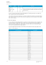
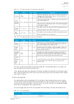
General settings
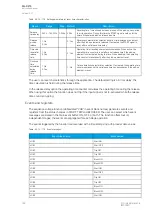
The following general settings define the general behavior of the function. These settings are static i.e.
it is not possible to change them by editing the setting group.
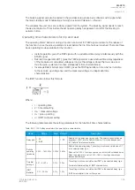
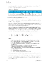
Table. 5.4.9 - 107. General settings of the function.
Name
Range Default
Description
U0> meas
input select
1:
Select
2:
U0Calc
3: U3
Input
4: U4
Input
1:
Select
Defines which available measured magnitude is used by the function. U0Calc calculates
the voltage from phase voltages.
Please note that U3 Input and U4 Input selections are available only if the channel has
been set to U0 mode at
Measurements
→
Transformers
→
VT module.
A
AQ
Q-C215
-C215
Instruction manual
Version: 2.07
© Arcteq Relays Ltd
IM00040
151


