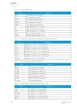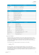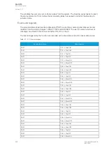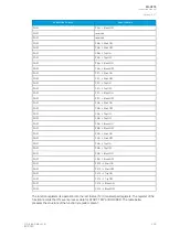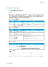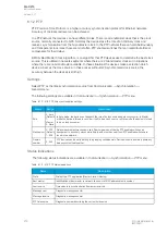
Reading events
Modbus protocol does not support time-stamped events by standard definition. This means that every
vendor must come up with their own definition how to transfer events from the device to the client. In
AQ-200 series devices events can be read from HR17...HR22 holding registers. HR17 contains the
event-code, HR18...20 contains the time-stamp in UTC, HR21 contains a sequential index and HR22 is
reserved for future expansion. See the Modbus Map for more information. The event-codes and their
meaning can be found from Event list (
Tools
→
Events ang Logs
→
Event list in setting tool). The event-
code in HR17 is 0 if no new events can be found in the device event-buffer. Every time HR17 is read
from client the event in event-buffer is consumed and on following read operation the next un-read
event information can be found from event registers. HR11…HR16 registers contains a back-up of last
read event. This is because some users want to double-check that no events were lost
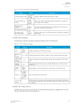
6.1.4 Modbus I/O
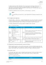
The Modbus I/O protocol can be selected to communicate on the available serial ports. The Modbus I/
O is actually a Modbus/RTU master implementation that is dedicated to communicating with serial
Modbus/RTU slaves such as RTD input modules. Up to three (3) Modbus/RTU slaves can be
connected to the same bus polled by the Modbus I/O implementation. These are named I/O Module A,
I/O Module B and I/O Module C. Each of the modules can be configured using parameters in the
following two tables.
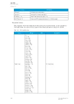
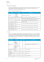
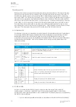
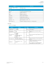
Table. 6.1.4 - 222. Module settings.
Name
Range
Description
I/O module X
address
0…247
Defines the Modbus unit address for the selected I/O Module (A, B, or C). If this setting
is set to "0", the selected module is not in use.
Module x
type
0: ADAM-4018+
1: ADAM-4015
Selects the module type.
Channels in
use
Channel
0…Channel 7 (or
None)
Selects the number of channels to be used by the module.
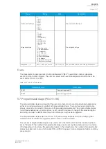
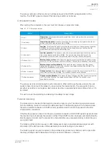
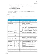
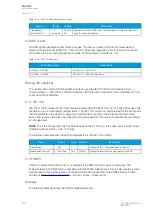
Table. 6.1.4 - 223. Channel settings.
Name
Range
Step Default
Description
T.C.
type
0: +/- 20mA
1: 4…20mA
2: Type J
3: Type K
4: Type T
5: Type E
6: Type R
7: Type S
-
1:
4…20mA
Selects the thermocouple or the mA input connected to the I/O module.
Types J, K, T and E are nickel-alloy thermocouples, while Types R and S are
platinum/rhodium-alloy thermocouples.
Input
value
-101.0…2
000.0
0.1
-
Displays the input value of the selected channel.
Input
status
0: Invalid
1: OK
-
-
Displays the input status of the selected channel.
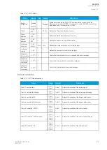
6.1.5 IEC 61850
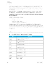
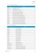
The user can enable the IEC 61850 protocol in device models that support this protocol at
Communication
→
Protocols
→
IEC61850. AQ-21x frame units support Edition 1 of IEC 61850.
AQ-25x frame units support both Edition 1 and 2 of IEC61850. The following services are supported by
IEC 61850 in Arcteq devices:
• Up to six data sets (predefined data sets can be edited with the IEC 61850 tool in AQtivate)
A
AQ
Q-C215
-C215
Instruction manual
Version: 2.07
274
© Arcteq Relays Ltd
IM00040

