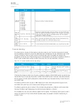
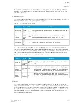

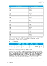
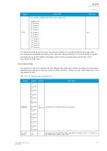

Table. 5.4.4 - 73. Pick-up settings.
Name
Description
Range
Step
Default
I0
set
Pick-up setting
0.0001…40.00 × I
n
0.0001 × I
n
1.20 × I
n
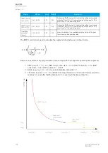
The pick-up activation of the function is not directly equal to the START signal generation of the
function. The START signal is allowed if the blocking condition is not active.
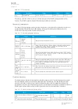
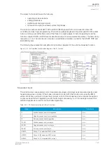
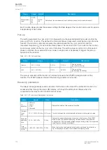
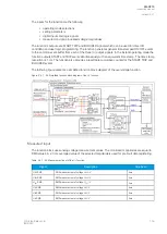
Read-only parameters
The relay's
Info page displays useful, real-time information on the state of the protection function. It is
accessed either through the relay's HMI display, or through the setting tool software when it is
connected to the relay and its Live Edit mode is active.
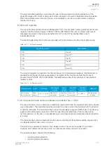
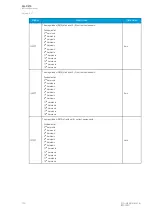
Table. 5.4.4 - 74. Information displayed by the function.
Name
Range
Step
Description
I0>
condition
0: Normal
1: Start
2: Trip
3: Blocked
-
Displays status of the protection function.
Detected
I0 angle
-360.00...360.00 deg
0.01
deg
Angle of I0 against reference. If phase voltages are available, positive sequence
voltage angle is used as reference. If voltages are not available, positive
sequence current angle is used as reference.
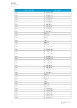
Detected
fault type
0: -
1: A-G-R
2: B-G-F
3: C-G-R
4: A-G-F
5: B-G-R
6: C-G-F
-
Displays the detected fault type and direction of previous fault. "A/B/C" stand for
one of the three phases. "G" stands for "ground". "F" stands for "forward" direction
and "R" stands for "reverse" direction.
Expected
operating
time
-1800.000...1800.000
s
0.005
s
Displays the expected operating time when a fault occurs. When IDMT mode is
used, the expected operating time depends on the measured current value. If
the measured current changes during a fault, the expected operating time
changes accordingly.
Time
remaining
to trip
0.000...1800.000 s
0.005
s
When the function has detected a fault and counts down time towards a trip, this
displays how much time is left before tripping occurs.
I
meas
/I
set
at the
moment
0.00...1250.00
0.01
The ratio between the measured current and the pick-up value.
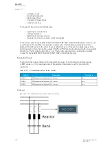
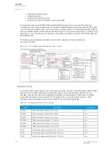
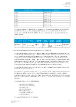
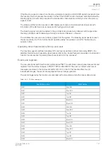
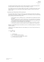
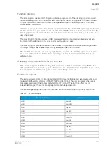
Function blocking
The block signal is checked in the beginning of each program cycle. The blocking signal is received
from the blocking matrix in the function's dedicated input. Additionally, non-directional earth fault
protection includes an internal inrush harmonic blocking option which is applied according to the
parameters set by the user. If the blocking signal is not activated when the pick-up element activates, a
START signal is generated and the function proceeds to the time characteristics calculation.
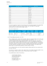
Table. 5.4.4 - 75. Internal inrush harmonic blocking settings.
Name
Description
Range
Step
Default
Inrush harmonic blocking (internal-only
trip)
2
nd
harmonic blocking enable/
disable
0: No
1: Yes
-
0: No
2
nd
harmonic block limit (Iharm/Ifund)
2
nd
harmonic blocking limit
0.10…50.00%I
fund
0.01%I
fund
0.01%I
fund
A
AQ
Q-C215
-C215
Instruction manual
Version: 2.07
120
© Arcteq Relays Ltd
IM00040


