PAGE 7
©2010 4Front Engineered Solutions, Inc. - APS Resource
AP4047 RA 11/10
INsTALLATION
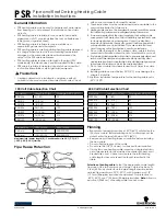
DOCK LEVELER PREPARATION
1. With the ramp properly secured by both
maintenance struts, carefully disassemble and
remove all parts of the ramp activation mechanism,
cross traffic leg mechanism, below dock chain
mechanism, lip extension mechanism, and holdown
assembly (if applicable).
2. Using the (2) 5/8” x 4” concrete anchor bolts
provided, anchor the rear frame of the dock leveler
to the pit floor. The anchor must penetrate at least
3” into the concrete. See Figure 8.
Always use full range toe guards on dock levelers
converted with hydraulic conversion. Failure to use
toe guards could result in serious injuries from a
descending dock leveler.
The Hydraulic Conversion Kit requires full range
toe guards for safe operation of the dock leveler. If
the dock leveler to be converted does not have full
range toe guards, install the toe guard kit included
with the HTC Kit.
Insure the full range toe guards cover the entire
dock leveler operating range. Re-adjust if
necessary.
3. Install full range sliding toe guards if applicable. In
some applications, it may be necessary to create
holes in the stationary toe guards for clearance of
the pivot and slider bolts. See Figure 9.
Figure 8
Figure 9
7. Place the lower strut tube into the subframe bracket
and fasten securely as shown using the hardware
provided. See Figures 6 and 7.
8. While extending the upper strut tube, swing both
tubes together upward, placing the tab into the
slot of the maintenance strut hanger located on
the ramp. Telescope both tubes until the holes line
up in both tubes and fasten as shown using the
hardware provided. See Figures 6 and 7.
9. Secure the upper tube to the maintenance strut
hanger using the hardware provided. If desired, a
keyed lockout (by others) may be used in place of
the hardware in position “A” only. See Figure 6.
Figure 7