background image


This    owner’s  manual  is  designed  to  assist  owners  and 

installers  with  the  operation,  maintenance  and 

installation 

of  your  new  water  filter.  It  is  our  sincere  hope  that  this  manual  is  clear,  concise  and  helpful. 

Detailed  instructions  on  general  operating  conditions,  pre

installation  and  installation  instructions,  start

up, 

and meter programming  are included. We have included a  troubleshooting guide, service  instructions and parts 

diagrams to assist  future needs. 


In the  event that  you  need professional assistance  for servicing your  water  filter,  please contact the  dealer


who installed this system.


Table OF Contents


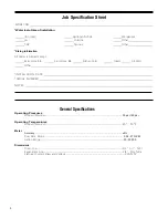
Job Specification Sheet 

................................................................................................................................. 

Page  3 

General  Specifications

.............................................................................................................................................. 3 

Pre

Instillation  Check  List

........................................................................................................................................ 4 

Bypass Valve Operation ........................................................................................................................................... 4 

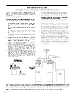
Installation Instructions 

............................................................................................................................................. 5 

Startup Instructions

................................................................................................................................................... 6 

Operating Conditions

................................................................................................................................................ 6 

Specifications 

........................................................................................................................................................... 6 

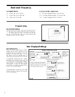
Programming 

............................................................................................................................................................ 7 

Displays/Settings 

...................................................................................................................................................... 7 

Regeneration Modes 

................................................................................................................................................ 8 

Disinfection 

............................................................................................................................................................... 8 

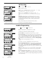
Set  Time of Day 

........................................................................................................................................................ 9 

Installation Displays/Settings

.................................................................................................................................... 9 

Filter Setup 

........................................................................................................................................................10-13 

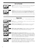
Diagnostics 

............................................................................................................................................................. 13 

Valve History........................................................................................................................................................... 14 

Cycle  Sequence 

................................................................................................................................................15-17 

Trouble Shooting 

...............................................................................................................................................18-19 

Ozone Trouble Shooting

......................................................................................................................................... 20 

Parts    Diagrams  &  Installation  Fittings

................................................................................................................21-

27 
Warranty ................................................................................................................................................................. 28 


Dealer Name   

  Phone   


Address   

  Email   


Summary of Contents for PurAzone A03

Page 1: ...PurAzone A03 Filtration PurAzone A03 Filtration Filter Manual Owner s Filter Manual 2013 2014...

Page 2: ...that you need professional assistance for servicing your water filter please contact the dealer who installed this system Table OF Contents Job Specification Sheet Page 3 General Specifications 3 Pre...

Page 3: ...se Bib Front Hose Bib Kitchen Cold Toilets All Cold Other INSTALLATION DATE SERIAL NUMBER NOTES Operating Pressures General Specifications Minimum Maximum 30 psi 120 psi Operating Temperatures Minimum...

Page 4: ...onnected per local codes Surge protection is recommended with all electrical controls existing Plumbing Condition of existing plumbing must be free from lime and iron build up Piping that is built up...

Page 5: ...5 Figure 2 Figure 4...

Page 6: ...ings bypass valve or control valve 4 a jumper ground wire should be installed between the inlet and outlet pipe whenever the metallic continuity of a water distribution piping system is interrupted In...

Page 7: ...ls vary depending on barometric pressure Manganese Limit 1 0 ppm amounts present over 1 0 ppm may gradually prevent iron removal Note For optimum manganese reduction pH should be greater than 8 5 Orga...

Page 8: ...7 Iron Blaster 10 Iron blaster 12 Iron blaster 13 10 x54 12 x52 13 x54 1 0 1 6 2 35 1 1 1 4 6 7 5 3 7 5 10 1 Water temps above 60 F will require a higher backwash rate Consult factory...

Page 9: ...ugh a regeneration cycle Capacity remaining is the number of gallons that will flashes in upper left corner of display between rotating display when RE GEN button pushed once GPM Flashes when the turb...

Page 10: ...r three seconds The system will begin to regenerate immediately The request cannot be cancelled You must cycle all the way through the cycles to make it stop PLEASE NOTE This will reset the meter rege...

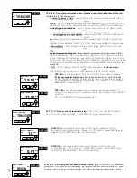
Page 11: ...ween regenerations If value set to oFF regeneration initiation is based solely on gallons used If value is set as a number allowable range from 1 to 28 a regeneration initiation will be called for on...

Page 12: ...XT to go to Step 6S Press REGEN to return to the previous step STEP 6 S Set Gallons Capacity using or button If value is set to oFF regeneration will be based solely on the day override set see Instal...

Page 13: ...t be shown Factory setting OFF Press NEXT to go to step 21S or other selection screens for relay settings RELAY 1 SET POINT STEP 9S STEP 9 S If off was selected in previous step this screen does not a...

Page 14: ...13 NEXT to go to Step 15S...

Page 15: ...that amount Range 20 to 500 minutes REGEN is also an option for lockout Relay initiates 2 minutes prior to regen and completes 1 minute after regen Access REGEN setting by pushing down arrow through a...

Page 16: ...o to Step 3D Press REGEN to exit Diagnostics SINCE LAST REGEN 342 GAL RESERVE HISTORY STEP 3D STEP 4D STEP 3D Volume since last regeneration This display shows gallons of water that has been treated s...

Page 17: ...ess and simultaneously for three seconds and release then press and simultaneously and release If screen in step 2VH does not appear in 5 seconds the lock on the valve is activated TOTAL DAYS 970 STeP...

Page 18: ...17 RETURN TO NORMAL MODE...

Page 19: ...CS OFF Factory Setting is OFF Press NEXT to go to Step 10CS alTernaTOr SYSTeM STeP 4cS STeP 4cS Twin alternating System Allows automatic alternation between two units to provide SeT alT a filtered wat...

Page 20: ...16 NEXT to go to Step 10CS...

Page 21: ...Step 11CS STeP 8cS Configuring the Control Valve for Water Reclamation Mode Select Reclama tion Enabled for control operation Motorized Alternating Valve will advance to Bypass at a set time after the...

Page 22: ...REGEN If the dP switch is closed a regeneration will be prevented from occurring OFF Factory setting is off Press NEXT to go to Step 14CS Press REGEN to return to previous step bacKWaSH SeT cYcle 1 rI...

Page 23: ...tached to board if not replace transformer Error Code 103 Motor ran too long C1 High drive forces on piston C1 Loosen drive cap gear 1 4 turn timed out trying to reach next position C2 Address high dr...

Page 24: ...20 place If not replace stack assembly B2 Mechanical Binding B2 Drive gear and reducing gears should spin freely replace if necessary...

Page 25: ...C D E Power outages Time of day not set correctly Time of regeneration incorrect Control valve set at on 0 immediate regeneration Control valve set at NORMAL on 0 A B C D E Reset control valve to cor...

Page 26: ...rror 106 107 or 116 117 occurs and the valve has not entered regeneration Ozone Generator Spare Replacement Parts Denotes recommended spare maintenance parts Followed by quantity per unit recommended...

Page 27: ...ate Distributor Part of Vortech Tank 7 Bypass Valve 1 101325 8 Inline Check Valve Kit 1 104174 includes 90 vertical adapter inline check valve 9 Ozone Generator 1 110110 10 Check Valve 1 110239 11 Tan...

Page 28: ...and plug back in This resets the electronics and establishes the service piston position The display should flash all wording then flash the software version ex 214 and then reset the valve to the se...

Page 29: ...jector Screen Injector Plug and O Ring 1 2 3 4 5 The injector plug and the injector each contain one 011 lower and 013 upper o ring Note For upflow position injector is located in the up hole and inje...

Page 30: ...019 1 6 102406 DLFC Retainer Assy 1 7 101591 101595 101598 101561 DLFC 5 3 gpm for 3 4 DLFC 7 5 gpm for 3 4 DLFC 9 0 gpm for 3 4 DLFC 10 0 gpm for 3 4 1 One DlFC must be used if 3 4 fitting is used D...

Page 31: ...Ring 2 3 102165 O Ring 215 2 4 102450 Bypass 1 Rotor 2 5 V3146 Bypass Cap 2 6 V3147 Bypass Handle 2 7 109479 Bypass Rotor Seal Retainer 2 8 102159 O Ring 135 2 9 102161 O Ring 112 2 10 102160 O Ring 2...

Page 32: ...cap Do not use a pipe wrench to tighten or loosen nuts or caps Do not place screwdriver in slots on caps and or tap with a hammer Do not use pipe dope or other sealants on threads Teflon tape must be...

Page 33: ...der nO deScrIPTIOn QTY 1 102141 Nut 1 Quick Connect 2 2 102437 Split Ring 2 3 102165 O Ring 215 2 4 106769 Fitting 3 4 Brass Sharkbite 2 1 4 110135 Fitting 3 4 Brass Sharkbite Asy Set of 2 1 4 1 4 1 2...

Page 34: ...28...
Reviews: