39
www.analogway.com
USER MANUAL
USER MANUAL
USER MANUAL
USER MANUAL
USER MANUAL
USER MANUAL
USER MANUAL
USER MANUAL
Adjustment
Description
Intensity
Transparency (opacity) of the layer
Pos X and Y
Horizontal and Vertical position of the layer.
0
is the center of the composition.
Scale
Size of the layer scaled on the full composition.
1
fills the composition horizontally.
Scale height
Height of the layer scaled on the
Scale
value.
1
keeps the original aspect ratio.
Rotation
Rotate the layer (360 degrees).
Rot. speed
Enable a continuous rotation of the layer. Set the speed of the rotation (set negative
value to rotate clockwise).
Draw mode
Set how this layer is drawn compared to other layers.
Note: For more information on position coordinates, see Canvas and coordinates page 74.
8.3.1
Draw modes
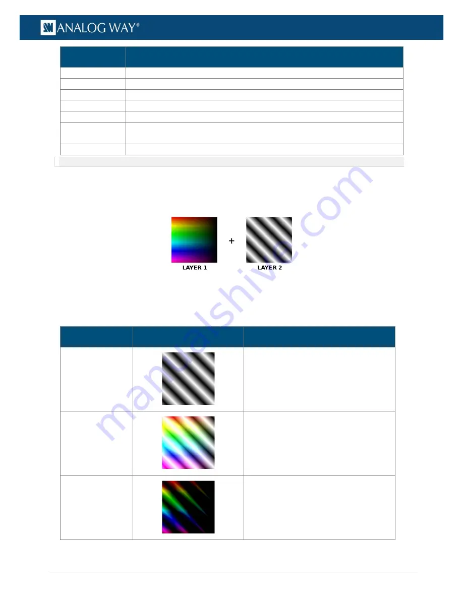
Draw mode determines how a layer is drawn and how it affects the layers beneath it.
The following table describes the different draw modes:
Fig. 25 -
Draw mode example images
-
Layer 2 (L2)
is always on top of
Layer 1 (L1)
.
-
The
Draw mode
of
L1
does not affect
L2
(
L1
is set to
Replace
in the following examples).
-
Changing the
Draw mode
of
Layer 2
gives different results.
Effect
Image
Description
Replace
Equation: L2
Default mode. Draw the layer on top of layers
below. The layers below the drawn layer are
not visible (except alpha channel).
Additive
Equation: L1+L2
Add the pixel values of the drawn layer to
layers below it (brighter image). White areas
in either layer stay white.
Subtract
Equation: L1-L2
Subtract the pixel values of the drawn layer
from layers below it (darker image). Black
areas on L2 leaves L1 unmodified. White
areas on L2 become black areas.


