


Color Active-Matrix LCD Mini-Touch Panels
Upgrading from G2 to G3 Firmware
159
VIA_PADSTACK
NET
VIA_PADSTACK
NET
VIA_PADSTACK
NET
NET
VIA_PADSTACK
NET
VIA_PADSTACK
NET
NET
NET
VIA_PADSTACK
NET
VIA_PADSTACK
NET
VIA_PADSTACK
NET
VIA_PADSTACK
NET
VIA_PADSTACK
NET
VIA_PADSTACK
NET
VIA_PADSTACK
NET
VIA_PADSTACK
NET
VIA_PADSTACK
NET
NET
VIA_PADSTACK
NET
VIA_PADSTACK
NET
VIA_PADSTACK
NET
NET
VIA_PADSTACK
NET
VIA_PADSTACK
NET
VIA_PADSTACK
NET
VIA_PADSTACK
NET
VIA_PADSTACK
NET
VIA_PADSTACK
NET
VIA_PADSTACK
NET
VIA_PADSTACK
NET
VIA_PADSTACK
NET
NET
VIA_PADSTACK
NET
VIA_PADSTACK
NET
NET
VIA_PADSTACK
NET
VIA_PADSTACK
NET
NET
NET
VIA_PADSTACK
NET
VIA_PADSTACK
NET
VIA_PADSTACK
NET
VIA_PADSTACK
NET
VIA_PADSTACK
NET
VIA_PADSTACK
NET
VIA_PADSTACK
NET
VIA_PADSTACK
NET
NET
VIA_PADSTACK
NET
VIA_PADSTACK
NET
NET
VIA_PADSTACK
NET
VIA_PADSTACK
NET
VIA_PADSTACK
NET
VIA_PADSTACK
NET
VIA_PADSTACK
NET
VIA_PADSTACK
NET
VIA_PADSTACK
NET
VIA_PADSTACK
NET
NET
VIA_PADSTACK
NET
VIA_PADSTACK
NET
NET
VIA_PADSTACK
NET
VIA_PADSTACK
NET
VIA_PADSTACK
NET
VIA_PADSTACK
NET
VIA_PADSTACK
NET
NET
VIA_PADSTACK
NET
VIA_PADSTACK
NET
VIA_PADSTACK
NET
NET
VIA_PADSTACK
NET
NET
VIA_PADSTACK
NET
VIA_PADSTACK
NET
NET
VIA_PADSTACK
NET
VIA_PADSTACK
NET
VIA_PADSTACK
NET
VIA_PADSTACK
NET
VIA_PADSTACK
NET
VIA_PADSTACK
NET
VIA_PADSTACK
NET
NET
NET
NET
VIA_PADSTACK
NET
NET
VIA_PADSTACK
NET
NET
NET
NET
VIA_PADSTACK
NET
VIA_PADSTACK
NET
NET
NET
NET
VIA_PADSTACK
NET
VIA_PADSTACK
NET
NET
VIA_PADSTACK
NET
NET
NET
VIA_PADSTACK
NET
VIA_PADSTACK
NET
VIA_PADSTACK
NET
VIA_PADSTACK
NET
VIA_PADSTACK
NET
VIA_PADSTACK
NET
VIA_PADSTACK
NET
VIA_PADSTACK
NET
VIA_PADSTACK
NET
NET
VIA_PADSTACK
NET
VIA_PADSTACK
NET
VIA_PADSTACK
NET
VIA_PADSTACK
NET
VIA_PADSTACK
NET
VIA_PADSTACK
NET
VIA_PADSTACK
NET
NET
VIA_PADSTACK
NET
VIA_PADSTACK
NET
VIA_PADSTACK
NET
VIA_PADSTACK
NET
VIA_PADSTACK
NET
NET
VIA_PADSTACK
NET
VIA_PADSTACK
NET
VIA_PADSTACK
NET
NET
VIA_PADSTACK
NET
VIA_PADSTACK
NET
VIA_PADSTACK
NET
VIA_PADSTACK
NET
VIA_PADSTACK
NET
VIA_PADSTACK
NET
VIA_PADSTACK
NET
NET
VIA_PADSTACK
NET
NET
VIA_PADSTACK
NET
VIA_PADSTACK
NET
VIA_PADSTACK
NET
VIA_PADSTACK
NET
VIA_PADSTACK
NET
VIA_PADSTACK
NET
VIA_PADSTACK
NET
VIA_PADSTACK
NET
VIA_PADSTACK
NET
VIA_PADSTACK
NET
VIA_PADSTACK
NET
VIA_PADSTACK
NET
VIA_PADSTACK
NET
VIA_PADSTACK
NET
NET
VIA_PADSTACK
NET
VIA_PADSTACK
NET
VIA_PADSTACK
NET
VIA_PADSTACK
NET
VIA_PADSTACK
NET
VIA_PADSTACK
NET
NET
VIA_PADSTACK
NET
NET
VIA_PADSTACK
NET
VIA_PADSTACK
NET
VIA_PADSTACK
NET
VIA_PADSTACK
NET
VIA_PADSTACK
NET
NET
NET
VIA_PADSTACK
NET
VIA_PADSTACK
NET
VIA_PADSTACK
NET
VIA_PADSTACK
NET
VIA_PADSTACK
NET
NET
NET
NET
NET
VIA_PADSTACK
NET
VIA_PADSTACK
NET
NET
VIA_PADSTACK
NET
NET
VIA_PADSTACK
NET
NET
NET
VIA_PADSTACK
NET
NET
VIA_PADSTACK
NET
VIA_PADSTACK
NET
VIA_PADSTACK
NET
NET
VIA_PADSTACK
NET
VIA_PADSTACK
NET
NET
VIA_PADSTACK
NET
VIA_PADSTACK
NET
VIA_PADSTACK
NET
VIA_PADSTACK
NET
VIA_PADSTACK
NET
VIA_PADSTACK
NET
VIA_PADSTACK
NET
VIA_PADSTACK
NET
VIA_PADSTACK
NET
VIA_PADSTACK
NET
VIA_PADSTACK
NET
VIA_PADSTACK
NET
VIA_PADSTACK
NET
VIA_PADSTACK
NET
COMPONENT
COMPONENT
COMPONENT
1
4
1
1
B2
B1
U24
U1
P1
U3
U19
U4
J2
J4
J2A
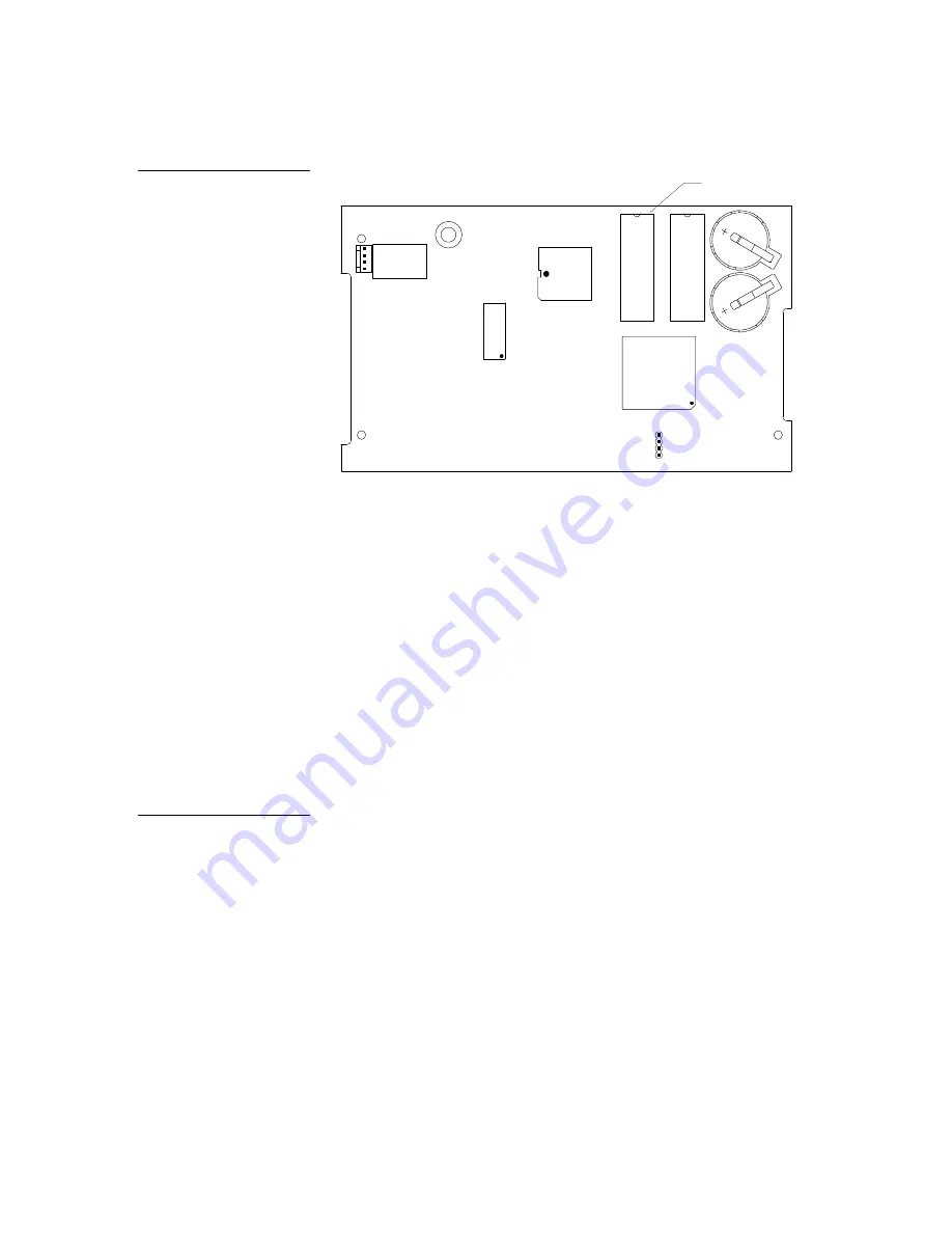
32-pin socket
E-PROM
Connector side of circuit card
To install the EPROMs onto the touch panel:
1.
Discharge the static electricity from your body by touching a grounded object.
2.
Remove the connectors and remove the touch panel from the Back Box or
equipment rack when replacing EPROMs on a circuit board.
3.
Flip the panel face down onto a soft cloth, and remove the seven Phillips-head
screws from the bottom panel. Then, gently remove the panel.
4.
For full-size panels remove the Phillips-head screw located in the center of the
circuit card.
5.
Gently tilt the circuit card down toward the connector side and pull backward
until you clear the connector housing. Then, slowly rotate the circuit card back-
ward until you can lay it down flat with the EPROM exposed.
6.
Remove the existing EPROM and replace it with one labeled version 3.X. Replace
the ‘E’ firmware chip with the upgrade ‘E’ firmware chip. Replace the ‘O’ firm-
ware chip with the ‘O’ upgrade.
7.
Carefully remove them by inserting a flathead screwdriver between the
EPROM and the connection site.
8.
Gently pry the EPROM from its connection base until it begins to loosen, at
which point you can pull it out.
9.
Repeat this process for the adjacent EPROM.
Figure 231
EPROM location on a mini-
touch panel UniMount and
rack-mount circuit boards
Note
On mini-touch panels, replace
the single firmware chip with
it's upgrade.
Summary of Contents for AXD-MCA
Page 30: ...22 Installing Mini Touch Panels Color Active Matrix LCD Mini Touch Panels ...
Page 68: ...60 Designing Touch Panel Pages Color Active Matrix LCD Mini Touch Panels ...
Page 130: ...122 Touch Panel Program Reference Color Active Matrix LCD Mini Touch Panels ...
Page 180: ...172 Memory Upgrade Color Active Matrix LCD Mini Touch Panels ...


