background image

Installation and Setup

40

Hardware Reference Manual – DXLink Twisted Pair™ Transmitters/Receiver

RJ-45 LEDs

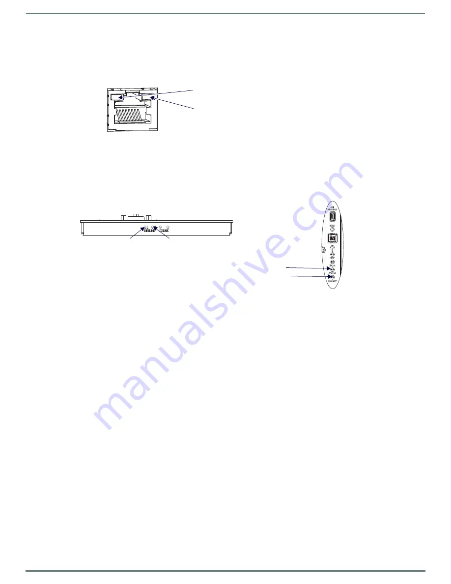
ICS LAN 10/100 Connector LEDs (modules only)

The following information applies to the LEDs on the ICS LAN 10/100 connector on the modules (FIG. 27). Note that #1 Toggle 

must

 be set to ON or ICS LAN functionality will not be provided.

NetLinx Connector LEDs (Wallplate TX/Decor Wallplate TX only)

The following information applies to the NetLinx LEDs on the bottom edge of the Wallplate TX and on the front of the Decor 

Wallplate TX, which reflect NetLinx communication and status via their DXLink lines (FIG. 28).



L/A 

or

 Link/Act Green LED

 – Link/Activity LED indicates network communication activity.



or

 Status Green Led

 – The Status LED indicates unit status.

TIP: 

If the Wallplate TX is installed in a location where it is difficult to check the LEDs on the bottom edge, slide a white piece of paper 

or a small mirror under the edge to view LED status.

DXLink Connector LEDs

The following information applies to the LEDs located on the DXLink (RJ-45) connectors on the rear of all DXLink Transmitters and 

Receivers. It also applies to the DXLink LEDs on the bottom edge of the Wallplate TX and the DXLink LEDs on the front of the Decor 

Wallplate TX.



Yellow:



On – Authenticated HDCP (handshaking has occurred successfully)



Flashing – Video active; no HDCP



Off – No Video



Green:



On – DXLink connection established (Endpoint Mode between TX/RX and switcher; Extender Mode between TX and RX)



Off – DXLink connection not established

The LEDs in FIG. 29 provide information for the DXLink connector. 

FIG. 27  

Module ICS LAN 10/100 connector LEDs

FIG. 28  

 Wallplate TX and Decor Wallplate TX NetLinx LEDs

RJ-45 Connector LEDs

Yellow LED

Green LED

ICS LAN 10/100 LEDs

(modules only)



Link/Activity (L/A) Green LED:



On – Link status is active (when the Ethernet 

cable is connected and terminated correctly)



Off – Link status is not active 



Speed Status (SPD) Yellow LED:



On – Speed status is 100 Mbps



Off – Speed status is 10 Mbps

On bottom edge of Wallplate TX

L/A - Green

S - Green

Front of Decor Wallplate TX


NetLinx LEDs

Status - Green

Link/Act - Green

DXLink Connector 

LEDs

Summary of Contents for AVB-TX-HDMI-DXLINK

Page 1: ...HARDWARE REFERENCE MANUAL DXLINK TWISTED PAIR TRANSMITTERS RECEIVER DX TX DX TX WP DX TX DWP DX RX AVB TX HDMI DXLINK ...

Page 2: ...les and the point where they exit from the apparatus 11 ONLY USE attachments accessories specified by the manufacturer 12 USE ONLY with a cart stand tripod bracket or table specified by the manufacturer or sold with the apparatus When a cart is used use caution when moving the cart apparatus combination to avoid injury from tip over 13 UNPLUG this apparatus during lightning storms or when unused f...

Page 3: ...ules These limits are designed to provide reasonable protection against harmful interference when the equipment is operated in a commercial environment This equipment generates uses and can radiate radio frequency energy and if it is not installed and used in accordance with the instruction manual it may cause harmful interference to radio communications Operation of this equipment in a residentia...

Page 4: ...HDMI TX Attaching Signal Transport and Control Cables 44 DX TX or HDMI TX Applying Power 44 DX RX Attaching Signal and Control Cables 45 DX RX Applying Power 46 Serial Data Transfer and IR Flow Control 47 Optional DX TX HDMI TX and DX RX Wiring for Serial Data Transfer 47 Optional DX TX HDMI TX and DX RX IR Control 48 ID Pushbutton Functions 49 DX RX Scaling Button and Scaling Modes 49 Detailed Ne...

Page 5: ...76 DXLink Transmitter USB SEND_COMMANDs 77 DXLink Receiver USB SEND_COMMANDs 78 Common DXLink Transmitter Receiver SEND_COMMANDs 78 DXLink System SEND_COMMANDs 79 SEND_STRING Escape Sequences 81 Enova DVX Switchers DXLink SEND_COMMANDs 82 Troubleshooting 83 Overview 83 Basic Troubleshooting 83 Determining HDCP Compliance 83 Power Issues 83 DXLink Connection Issues 84 Network Setup Issues 85 Techni...

Page 6: ...ut 104 HD 15 Connector Cable Pinout 105 DVI Pinout for DVI to HDMI Cable Adapter 106 Appendix E Supported Input Resolutions 107 Available Pixel Display and Refresh Rate 107 Appendix F Supported Output Resolutions 110 HDMI and DVI Supported Output Resolutions 110 Digital Video Output Resolution Support 111 Appendix G Ground Wire Attachment 115 Applicability 115 Attaching a Ground Wire to a Common E...

Page 7: ...n no digital video is present 2 Active ICSP command video input selection from a bound NetLinx Central Controller Both the video and audio are transported over twisted pair cable to an Enova DGX Digital Media Switcher an applicable Enova DVX Solution to a DX RX or directly to a DX RX The 232 port RS 232 on the DX TX supports bidirectional serial data via the twisted pair cable to from the 232 port...

Page 8: ... The Transmitters and the Receiver are compatible with the DXLink products listed in the three tables following Enova DGX Solutions and DXLink Functions The following table shows which Enova DVX products support specific DXLink functions Inputs and outputs up to 8 16 32 or 64 depending on the system in increments of 4 inputs or outputs per board For power budget information for system planning whe...

Page 9: ...he 232 port RS 232 serial supports bidirectional transfer of serial data between Master and TX or RX Endpoint Mode or between TX and RX Extender Mode The IR port supports bidirectional transfer of IR data between Master and TX or RX Endpoint Mode or between TX and RX Extender Mode Power over DXLink twisted pair cable support when used with a switcher or with an approved AMX Power over DXLink devic...

Page 10: ... port This port USB mini B connector supports DGX Configuration Software for programming a customer VGA EDID IR LEDs TX and RX LEDs indicate active IR communication 232 LEDs RS 232 serial TX and RX LEDs indicate active serial communication NetLinx LEDs Link Act LED indicates network communication activity The Status LED indicates unit status CEC LED CEC is not currently supported USB LED When illu...

Page 11: ...audio Audio LED Indicates the unit is configured to pass analog audio coupled with digital or analog video path USB Host port Mini B USB connector supports USB host for receiving keyboard mouse commands from a specific RX For USB port information see page 18 Power LED Indicates when the Wallplate TX is powered on DX TX and HDMI TX Indicator LEDs LED Normal Display Indicates Power Green Power is ap...

Page 12: ... adapter When more than one audio signal is present HDMI embedded audio takes precedence over analog audio Power LED Indicates when the Decor Wallplate TX is powered on Audio LED Indicates the unit is configured to pass analog audio coupled with digital or analog video path Analog Video LEDs Illuminates when the Decor Wallplate TX is configured to pass analog video composite or Y C Y Pb Pr or RGB ...

Page 13: ...MMAND information see page 68 C composite or Y C two component Y PB PR or RGB three component RGBHV five component or RGBS four component Audio Green The Wallplate TX and Decor Wallplate TX have been configured to pass analog audio as the audio source being embedded on the DXLink output connection coupled with either the analog or digital video input path for SEND_COMMAND information see page 72 P...

Page 14: ... is connected an audio format SEND_COMMAND is available the Transmitter must be set for network connectivity via 3 Toggle to select the desired audio source see page 72 ICS LAN 10 100 Connector The ICS LAN 10 100 RJ 45 connector provides for Ethernet 10 100 connectivity e g receiving SEND_COMMANDs and downloading firmware update files For pinout and LED information see page 39 RS 232 Serial Port T...

Page 15: ... Output Connector The DXLink RJ 45 connectors transport digital video embedded audio bidirectional control and Ethernet SEND_COMMANDs only over twisted pair cable to DXLink devices or boards including digitally transcoded analog video signals The DXLink path supports HDCP In addition the Wallplate TX and Decor Wallplate TX receive power over the DXLink line from an Enova DGX Switcher some Enova DV...

Page 16: ...is detected NOTE For detailed behavior of the NetLinx Link Act and Status LEDs on the module s front see page 50 For detailed behavior of the RJ 45 connectors LEDs on the module s rear see page 40 Receiver Rear View The following components are located on the rear of the DX RX left to right Power Jack The power receptacle is a 2 1 mm DC jack for connecting power Power can come from a locally conne...

Page 17: ... a 2 way mini Phoenix connector In addition to being directly connected to a device this port can be connected as an independent native NetLinx control port from a networked NetLinx Central Controller USB Port The USB A port on the RX supports keyboard mouse This port is used in conjunction with the USB B Host port on the HDMI TX which supports a USB device and connects to the PC For USB port info...

Page 18: ...ar of the DX RX supports passthrough information from the USB Host port on the Transmitter to an HID Human Interface Device which is most commonly a keyboard or mouse HID Devices and Windows 8 Windows 8 will not wake up from a DXLink connected keyboard or mouse unless the properties for the HID device are set to allow the device to wake the computer Note that even a hot plug of the USB cable will ...

Page 19: ...then the HDMI output on the Receiver will not send the signal This does not affect additional displays the source may be routed to i e HDCP compliant displays will still show content from the source device even when the source device is also routed to non compliant displays Non compliant devices can be easily identified because they display a dark red image or an orange image to indicate the authe...

Page 20: ...tion settings are turned OFF Static IP Mode This mode configures the network connection to one stable IP address the device will use continuously DHCP Mode This mode configures the network connection to choose a new IP address for each network session To enable network capability see Network Configuration on page 52 ID Mode ID Identify Mode refers to the protocol for enabling a user to establish d...

Page 21: ...PORTANT If auto setup is being used Telnet is the only way to access some of the network settings Also note that some network settings will disable auto setup For additional information on the auto setup feature see the Hardware Reference Manual Enova DGX 100 Series Digital Media Switchers IR SEND_COMMAND Modes IR SEND_COMMAND Modes refer to displaying and setting the IR port active system setting...

Page 22: ...gital Media Switcher use the Enova DGX Configuration Tool located at www amx com enova to determine the power requirements of the configuration and whether any of the DXLink Transmitters or Receivers should be powered with the local power supplies or the supported Power over DXLink injector The configuration tool contains instructions on how to determine power requirements Power Consumption Local ...

Page 23: ...he walls of the structure s are physically connected and the structure s share a single ground reference For more details and helpful cabling information reference the white paper titled Cabling for Success with DXLink available at www amx com or contact your AMX representative Modules Airflow Convection openings on top of case Transmitters and Receiver Inter compatibility All DXLink Transmitters ...

Page 24: ...iver USB HID Wallplate TX and Decor Wallplate TX DX TX WP 1 USB Mini B Host DX TX DWP 1 USB Mini AB Host Connect a DXLink Twisted Pair Decor Transmitter to a PC and emulate keyboard and mouse commands from a DXLink Twisted Pair Receiver or a DXLink Fiber Receiver USB HID DX RX 1 USB Type A connector Device Connect a keyboard and mouse and send commands to a PC connected to a DXLink Twisted Pair Tr...

Page 25: ...tial Input Re clocking CDR Yes Input Equalization Yes adaptive Input Connector HDMI Type A female Propagation Delay typical 5 μs RX Output Signal Type HDMI DVI D Single Link with a DVI to HDMI cable adapter Output Scaling SmartScale Manual Configuration Bypass SmartScale Output Resolution Support All resolutions between 480p and 1920x1200 60Hz via automatic SmartScale query of the display s prefer...

Page 26: ...rmats Local Audio Specifications Parameter Value TX Input Signal Types Stereo analog S PDIF Video signal must be present to pass audio Analog Input Level max 2 dBu unbalanced Analog Input Impedance 10 kohms Analog to Digital Conversion 48 kHz sample rate 24 bit S PDIF Audio Format Support Dolby Digital DTS 2 CH L PCM S PDIF Resolution 16 to 24 bit S PDIF Sample Rate 32 kHz 44 1 kHz 48 kHz 96 kHz S...

Page 27: ...cing equipment is placed directly above or below the modules CAUTION To prevent overheating avoid placing high heat producing equipment directly above or below the modules We recommend allowing plenty of clearance above the vent holes on top of the modules Do not place anything directly on top of the modules that would restrict airflow through the vent holes on top Reliable Earthing Grounding Reli...

Page 28: ...Controller see page 30 Extender Mode Standalone A standalone DXLink TX RX pair are connected directly to each other as a simple extender solution see page 31 The switcher can be either an Enova DGX Switcher or an applicable Enova DVX Solution see Product Compatibility Tables on page 8 Endpoint Mode Switcher Example of Typical System Setup The primary function of the Transmitters and Receivers is t...

Page 29: ... the appropriate DGX Fiber Module For information see the DGX Fiber Module s manual Options for System Setup with Enova DVX Solutions The following table contains options for using DXLink Transmitters and Receivers in conjunction with DXLink Input and Output connectors on Enova DVX Solutions Note that on the input side four Transmitter options are available The Transmitters used with the inputs ca...

Page 30: ...ler Twisted pair cable Twisted pair cable Twisted pair cable Twisted pair cable Source Destination Destination Destination Destination Source Source Source HDMI cable HDMI cable HDMI cable HDMI cable HDMI cable HDMI cable HDMI cable HDMI cable Twisted pair cable Switcher Switcher Switcher TX acts like a repeater TX acts like a sink TX acts like a sink Example A When a Receiver acts like a source i...

Page 31: ... POE AT TC using power via the DXLink line to maintain the switcher s power redundancy we recommend that you Determine the power budget based on the Input Output boards used and the quantity of powered endpoints modules see below Do not use the local DC power jack on the module even if the local power adapter is turned off NOTE When using DXLink Power from an Enova DGX Switcher we recommend wiring...

Page 32: ...erational from a normal non redundant system capability perspective In the Event of a Power Supply Failure If an Enova DGX power supply fails check the table below to determine which condition applies and any actions that may be required In all of the situations above the power supply should be replaced as soon as possible to restore power redundancy to the system or to allow the system to become ...

Page 33: ...s for common scenarios is on the next three pages In NetLinx Studio the DXLink TXs and RXs can be bound to the integrated Master by right clicking on the device and selecting Network Bind Unbind Device This is considered the traditional method of binding If the integrated Master runs on a 100 Series CPU see the Hardware Reference Manual Enova DGX 100 Series Digital Media Switchers for auto setup i...

Page 34: ...over the ICS LAN 10 100 port is disabled ON When the 1 Toggle is set to ON network activity over the ICS LAN 10 100 port is enabled Installation Options Option A For a network connection between a Transmitter and a Receiver where only one of them is connected to a LAN set the 1 Toggle to ON for the unit that is connected to the network CAUTION Option A Do not connect both the Transmitter and the R...

Page 35: ... Endpoint Mode Only one must be connected via the ICS LAN 10 100 port to the Master or to a LAN with the Master on it This requires 1 Toggle to be ON to enable the ICS LAN port 2 Toggle needs to be ON to place the modules in Endpoint Mode if needed and 3 Toggle needs to be ON to enable network connectivity NOTE On either setting the DXLink Mode may be set via SEND_COMMANDs see page 79 When 2 Toggl...

Page 36: ...We recommend allowing plenty of clearance above the vent holes on top of the modules Do not place anything directly on top of the modules that would restrict airflow through the vent holes on top The DX TX HDMI TX and DX RX are classified as V Style modules which have optional V Style mounting hardware These versatile mounting options include rack trays and mounting brackets for desktops under des...

Page 37: ...blem is likely caused by the use of a single phase powered system that does not provide an earth ground for a source or destination s chassis and shields This can inject unnecessary AC voltage on the HDMI cable shield that can lead to DXLink signal integrity issues To check for indications of this type of power in the system look for a two pronged plug or a cord that has only two wires Items Requi...

Page 38: ...X and Decor Wallplate TX each have a designated ground screw on the rear look for the grounding symbol If the DXLink Wallplate does not have a designated screw use the screw directly above the DXLink RJ 45 connector on the rear for grounding To attach a ground wire to a DXLink Wallplate or Decor Wallplate TX 1 If powered power down the unit by removing the DXLink cable from the rear 2 Remove the g...

Page 39: ...red rather than leaving any excess cable in a service loop For complete cable specifications see page 23 For more details and helpful cabling information reference the white paper titled Cabling for Success with DXLink available at www amx com or contact your AMX representative Common building is defined as Where the walls of the structure s are physically connected and the structure s share a sin...

Page 40: ...nector LEDs The following information applies to the LEDs located on the DXLink RJ 45 connectors on the rear of all DXLink Transmitters and Receivers It also applies to the DXLink LEDs on the bottom edge of the Wallplate TX and the DXLink LEDs on the front of the Decor Wallplate TX Yellow On Authenticated HDCP handshaking has occurred successfully Flashing Video active no HDCP Off No Video Green O...

Page 41: ... audio to be sent out of the analog stereo audio connector on the DX RX the audio must have originated or be embedded in the HDMI signal on the Enova DGX Digital Media Switcher Enova DVX Solution or Transmitter as a 2 channel signal either analog stereo or 2 channel L PCM Multi channel 2 channel L PCM formats will pass incomplete audio only 2 of the multiple channels will be sent All other audio f...

Page 42: ...the rear of the unit b Attach unit to the back box with four screws through the large screw holes IMPORTANT If a network connection is required set 3 Toggle to ON see page 35 3 Wallplate TX Reattach unit to the mounting bracket with the four screws removed in Step 2a Decor Wallplate TX a Check LEDs for normal display see the table on the next page b Attach standard decor style front cover plate cu...

Page 43: ...l display as stated in the table above check all of the connections and the suggestions in the Troubleshooting chapter see page 83 before contacting technical support see page 86 Wallplate TX and Decor Wallplate TX Indicator LEDs LEDs Normal Display Indicates Digital Video default Green The Wallplate TX and Decor Wallplate TX have been configured to pass HDMI for SEND_COMMAND information see page ...

Page 44: ...ces the module in ID Mode for setting the NetLinx ID device only and provides additional functionality such as placing the device in Static IP Mode or DHCP Mode For complete information see page 56 DX TX or HDMI TX Applying Power IMPORTANT If desktop power is used to power the Transmitter only the provided desktop power supply should be used and it must not be altered in any way Remote power can o...

Page 45: ...RTANT Before attaching cables be sure to set DIP switch s toggles if necessary see page 36 IMPORTANT Do not use the RJ 45 connector labeled DXLink for connecting to a standard Ethernet Network NOTE Power IR and RS 232 ports are covered in their own sections To attach signal transport and control cables to the HDMI RX 1 DXLink input connector Attach a twisted pair cable from the switcher or DX TX o...

Page 46: ...RX illuminates a constant green which indicates a ready state Some of the additional LEDs will also turn a turn a constant green For normal LED display see the table below IMPORTANT If any Receivers are being powered through an Enova DGX we recommend determining the power budget to maintain power redundancy for the system see page 44 DX RX Indicator LEDs The LED indicators are listed in the table ...

Page 47: ...or serial strings to pass through a standalone TX and RX pair in Extender Mode without a NetLinx Master acting as the host DIP switch 2 Toggle must be set to OFF on each module The RS 232 port labels are relative to the data flow On the DX TX or HDMI TX data enters the system at the RX label and leaves the system at the TX label on the Receiver FIG 34 The flow is reversed from the Receiver to the ...

Page 48: ... the jack on the IR03 External IR Receiver Module cable FG IR03 to the IR RX port on the module 2 Run the cable and attach the IR receiver bud so that it has a clear line of sight with the intended remote control device CC NIRC NetLinx IR Emitter Cable not included To connect an IR Emitter to a module 1 Connect the Phoenix connector on the CC NIRC NetLinx IR Emitter cable FG10 000 11 to the IR TX ...

Page 49: ... signal to display over the destination device without altering the signal s resolution NOTE Interlaced and progressive video are supported into the Transmitters progressive is only supported out of the Receiver unless it is in the Bypass mode which is non scaling Auto Mode At initial power up the DX RX defaults to the Auto scaling option NOTE When the output cable is disconnected from the DX RX o...

Page 50: ...blink then normal operation ON Normal Boot DHCP no server NOTE This state continues until a valid IP address is obtained OFF during light show then normal operation OFF until connected to Master Fast blink continues only during light show then ON until first blink from Master Normal Boot Static IP NOTE This state continues until the device finishes its light show ID Pushbutton Boot and NetLinx LED...

Page 51: ...ssed between them When two switching systems with DXLink support are connected via their DXLink ports only video and audio will be passed through the DXLink connection When a DXLink input or output on one switching system determines that it is connected to a DXLink input or output on another switching system the DXLink port will automatically disable all Ethernet power and control on that connecti...

Page 52: ...must be ON before the device is accessible via SEND_COMMANDs DHCP Mode requires a connection to a network with a DHCP server located on it This connection can be either indirect or direct Indirect connection In the case of an Enova DGX Digital Media Switcher or an Enova DVX Solution Endpoint Mode that is connected to a DHCP server device the DHCP connection can be propagated through the system s D...

Page 53: ...e used for initial network configuration of the DXLink Modules The default Telnet port is 23 Telnet is enabled by default A value of 0 disables the telnet server For details see Appendix B Telnet Terminal Commands on page 91 The appendix also includes a section on Master Connection Modes on page 98 If you set the Telnet port to 0 to disable it you will need to perform a factory reset using the ID ...

Page 54: ... DXLink device During this time the DXLink device will reboot and all functions including video and audio delivery will be disabled while the reboot occurs This process takes up to 45 seconds to complete This functionality is an option intended to be a safety net for the rare occasions when a device falls offline and remains there for a long enough period of time that the likelihood of the device ...

Page 55: ...P and UDP URL modes 1319 Friendly Name blank NOTE If the Friendly Name is non blank both Friendly Name and Location are concatenated to make NDPSTRING2 otherwise NDPSTRING2 is generated from the unit s serial number Location blank Stored MAC Address of Master for NDP binding 00 00 00 00 00 00 ICSP Device Number 0 0 receive dynamic device number from Master System Number 0 Telnet Port 23 A value of...

Page 56: ...ON see page 35 the modules automatically use DHCP with link local fallback However you can use a static IP address which can be set via a Telnet command SET IP or you can use the factory default static IP address The default static IP address can be recalled at any time by resetting the unit to its factory default configuration see page 57 The default dynamic DHCP address is 169 254 2 2 The ID Pus...

Page 57: ...nx device in the named system e g pressing the ID Pushbutton on the Receiver The device that generates the first event is the device that will be identified 6 Briefly press and release the ID Pushbutton on the Transmitter or Receiver The Transmitter or Receiver will exhibit the following behavior Respond with an ID Mode address response Report its old address offline Report its new address online ...

Page 58: ...m the unit to abort the procedure remember power can be applied via the external power supply or over DXLink so one or both sources of power may need to be removed Restore the Factory Firmware Image and Factory Default Parameters During power up if the ID Pushbutton is held until the Control NetLinx LEDs toggle back and forth in unison approximately 30 times 10 slow 20 fast and then released when ...

Page 59: ... being unbound For a complete list of factory parameters see the table on page 55 3 Once all actions in Step 3 are completed the LEDs all turn off indicating the unit is ready to reboot The unit automatically reboots to complete the process TIP To monitor the ID Pushbutton boot state of a module see the ID Pushbutton Boot and NetLinx LED Behavior table below ID Pushbutton Boot State and LED Behavi...

Page 60: ...ion with a switcher the switcher s integrated Master is used for the IRL file transfer FIG 38 shows a Transmitter and a Receiver bound to the integrated Master in an Enova DGX 32 in NetLinx Studio s OnLine Tree Follow the instructions on the top of page 61 to prepare for IRL file transfer and the instructions on page 62 for the actual transfer FIG 38 NetLinx Studio Integrated Master Enova DGX 32 D...

Page 61: ...nected from the switcher s integrated Master to the network e g from the LAN 100 1000 port on the Enova DGX to a LAN b Verify that the target Transmitter or Receiver is connected via its DXLink connector to a DXLink Input or Output Board respectively on the switcher c Verify that the switcher is powered on 5 Launch NetLinx Studio and open the OnLine Tree 6 Bind the target Transmitter or Receiver t...

Page 62: ...NetLinx Studio select Tools File Transfer to open the File Transfer dialog box 2 Click Add to open the Select Files for File Transfer dialog box 3 Open the Other tab if the file you want to transfer is not included in the open workspace The Other tab consists of a display of different types of files that can be transferred to a Master or System devices on the bus 4 Select the type of file in this ...

Page 63: ...File Transfer dialog box The selected IRL file and its mapping information are indicated in the File and Mapping lists 10 Click OK to close the Select Files for File Transfer dialog box and return to the File Transfer dialog box The IRL file appears in the File queue 11 Click Send to transfer the file to the Transmitter or Receiver that the file is mapped to Additional Documentation For additional...

Page 64: ...s page 78 Common DXLink Transmitter Receiver SEND_COMMANDs page 78 DXLink System SEND_COMMANDs page 79 SEND_STRING Escape Sequences page 81 Also provided in this chapter are DXLink SEND_COMMANDs specifically for Enova DVX Switchers see page 82 NOTE For a listing of all supported Telnet commands see page 93 Device Numbering and Ports Each DXLink Transmitter and Receiver has its own Device Number wh...

Page 65: ...rol system NOTE Since not all devices support both upper and lower case for best results all commands and parameters should be sent in upper case FIG 39 NetLinx Studio OnLine Tree Ports 1 through 7 on a DXLink Transmitter and Receiver Channel Function 255 This channel On indicates that the DXLink Module has a valid UTP twisted pair cable connection to a switcher with an Integrated Master If the ch...

Page 66: ...rizontal x vertical rate VIDOUT_RES_REF Sets the resolution and refresh rate of the video through the Receiver and also sets the Scaling Mode to MANUAL IMPORTANT The valid responses used must come from the Resolution Names listed in the table in the Supported Output Resolutions appendix on page 110 NOTE The default for Manual Mode is 1280x1024 60 Syntax SEND_COMMAND DEV VIDOUT_RES_REF horizontal x...

Page 67: ... image Anamorphic This option is used with anamorphic formatted video sources so that images appear correctly on the display VIDOUT_ASPECT_RATIO Sets the aspect ratio preference of the video through the Receiver to Stretch Maintain Zoom or Anamorphic For explanations of the ratio options see page 67 Syntax SEND_COMMAND DEV VIDOUT_ASPECT_RATIO ratio Valid responses ratio STRETCH MAINTAIN ZOOM ANAMO...

Page 68: ... ALL Syntax SEND_COMMAND DEV AUDOUT_FORMAT format Valid response format HDMI ANALOG ALL Example SEND_COMMAND dvRX AUDOUT_FORMAT ANALOG Video SEND_COMMANDs Transmitters Command Description VIDIN_AUTO_SELECT Requests setting for the Auto Select mode for the video input signal on the DX TX Wallplate TX or Decor Wallplate TX Enable or Disable NOTE This command applies to all DXLink Transmitters except...

Page 69: ...ample SEND_COMMAND dvMFTX VIDIN_STATUS Returns a COMMAND of the form VIDIN_STATUS status VIDIN_FORMAT Requests the video format on the Transmitter NOTE All DXLink Transmitters except the HDMI TX support component S Video composite and VGA signals NOTE Send to Port 7 or Port 8 Syntax SEND_COMMAND DEV VIDIN_FORMAT Valid response format port 8 COMPONENT S VIDEO COMPOSITE VGA format port 7 HDMI DVI Ex...

Page 70: ...refresh rates see the tables starting on page 107 Examples SEND_COMMAND dvMFTX VIDIN_PREF_EDID 1920x1080p 60 VIDIN_EDID Requests which EDID is being presented to the source on the video port addressed by the D P S IMPORTANT Send to Port 8 Syntax SEND_COMMAND DEV VIDIN_EDID Example SEND_COMMAND VIDEO_INPUT_1 VIDIN_EDID Returns a COMMAND of the form VIDIN_EDID source See the VIDIN_EDID command for t...

Page 71: ...input port addressed by the D P S NOTE This command applies to all DXLink Transmitters except the HDMI TX IMPORTANT Send to Port 8 Syntax SEND_COMMAND DEV VIDIN_VSHIFT value Valid responses value 7 7 Example SEND_COMMAND dvMFTX VIDIN_VSHIFT 2 Sets the vertical shifting of analog video input port 1 based on D P S to 2 shift upward SEND_COMMAND dvMFTX VIDIN_VSHIFT 3 Sets the vertical shifting of ana...

Page 72: ...SEND_COMMAND DEV AUDIN_FORMAT_AUTO ENABLE DISABLE Example SEND_COMMAND dvTX AUDIN_FORMAT_AUTO ENABLE AUDIN_FORMAT Requests the setting for the audio source format Syntax SEND_COMMAND DEV AUDIN_FORMAT Valid response format HDMI SPDIF ANALOG Example SEND_COMMAND dvTX AUDIN_FORMAT Returns a COMMAND of the form AUDIN_FORMAT format AUDIN_FORMAT Selects the audio input source that will be embedded on th...

Page 73: ...alid response channel number 0 to 199 channels Example SEND_COMMAND IR_1 CH 18 The IR port on the DXLink TX or RX performs the following Transmits IR signals for 1 IR code 11 The transmit time is set with the CTON command Waits until the time set with the CTOF command elapses Transmits IR signals for 8 IR code 18 Waits for the time set with the CTOF command to elapse If the IR code for Enter IR co...

Page 74: ...the designated port Syntax SEND_COMMAND DEV IROFF Example SEND_COMMAND IR_1 IROFF Immediately halts and clears all IR output signals on the IR port SET BAUD Use to set the IR communication parameters NOTE Before sending the SET BAUD command you must set the IR port to Data mode for the SET MODE command see page 74 NOTE This value is not saved in non volatile memory and is reset to default 9600 N 8...

Page 75: ...smits the IR code as 3 4 enter SEND_COMMAND IR_1 XCH 343 Transmits the IR code as 3 4 3 enter Mode 1 Example x x x enter SEND_COMMAND IR_1 XCH 3 Transmits the IR code as 0 0 3 enter SEND_COMMAND IR_1 XCH 34 Transmits the IR code as 0 3 4 enter SEND_COMMAND IR_1 XCH 343 Transmits the IR code as 3 4 3 enter Mode 2 Example x x x SEND_COMMAND IR_1 XCH 3 Transmits the IR code as 0 0 3 SEND_COMMAND IR_1...

Page 76: ...response time 0 to 10000 1 second Example SEND_COMMAND dvRXRS232 CHARD 10 Sets a 1 millisecond delay between all transmitted characters CHARDM Set the delay time between all transmitted characters to the value specified in 1 millisecond increments Syntax SEND_COMMAND DEV CHARDM time Valid response time 0 to 1000 1 second Example SEND_COMMAND dvRXRS232 CHARDM 10 Sets a 10 millisecond delay between ...

Page 77: ... serial communication NOTE This value is not saved in non volatile memory and is reset to default 9600 N 8 1 at power up Syntax SEND_COMMAND DEV SET BAUD baud parity data stop Valid responses baud 115200 76800 57600 38400 19200 9600 4800 2400 1200 600 300 150 parity N none O odd E even M mark S space data 7 or 8 data bits stop 1 or 2 stop bits NOTE The only valid 9 bit combination is baud N 9 1 Ex...

Page 78: ...ddress To redirect to a new host device Transmitter send the new IP address or hostname Common NetLinx SEND_COMMANDs Transmitters and Receivers Command Description FWVERSION Requests the firmware version of the TX or RX Syntax SEND_COMMAND DEV FWVERSION Example SEND_COMMAND dvRX FWVERSION Returns a COMMAND of the form FWVERSION version string LED DIS Disable all LEDs to the right of the Program po...

Page 79: ...he form DXLINKOUT_LINK_STATUS DISCONNECTED CONNECTED DXLINKIN_QUALITY Requests a value that represents the quality of the signal between a DXLink Input Port and an Endpoint Syntax SEND_COMMAND DEV DXLINKIN_QUALITY Example SEND_COMMAND dvTX DXLINKIN_QUALITY Returns a COMMAND string of the form DXLINKIN_QUALITY 22 DXLINKOUT_QUALITY Requests a value that represents the quality of the signal between a...

Page 80: ...ard will not get reset to default AUTO but will remain as whatever was last persisted All Transmitters Clears the persisted setting for the audio and video formats and restores them to their factory defaults Also restores the preferred EDID to the factory default on the HD 15 input to 1920x1080P 60 Syntax SEND_COMMAND DEV FACTORYAV Example SEND_COMMAND dvTX FACTORYAV NOTE A reboot is required afte...

Page 81: ... time Valid response time 1 to 255 measured in 100 microsecond increments Example SEND_STRING RS232_1 27 17 10 Sends a break character of 1 millisecond to the RS232_1 device 27 18 0 Clear the ninth data bit by setting it to 0 on all character transmissions Used in conjunction with the B9MON command see page 76 Syntax 27 18 0 Example SEND_STRING RS232_1 27 18 0 Sets the RS232_1 device s ninth data ...

Page 82: ...MMAND SWITCHER DXLINK_ETH Returns a COMMAND of the form DXLINK_ETH AUTO OFF DXLINK_ETH Controls Ethernet traffic through the DXLink output card on an Enova DVX Switcher This command instructs the DXLink output card on an Enova DVX Switcher to disable Ethernet traffic or go to Auto mode In Auto mode Ethernet traffic is controlled after negotiation through PDIF Syntax SEND_COMMAND DEV DXLINK_ETH AUT...

Page 83: ...ction with an Enova DGX Switcher we suggest checking the troubleshooting information in that product s manual Enova DVX Solutions When DXLink units are used in conjunction with an Enova DVX Solution we suggest pressing the Status button on the front panel and using the UP and DOWN navigational buttons to scroll through the menu options to Diagnostic Codes the codes can be helpful for technical sup...

Page 84: ... Transmitters Receivers intended to be powered via the DXLink line do not have a DC jack plugged in even if the local power adapter is turned off This can cause inadvertent ground loops that can negatively affect DXLink power sensing circuits DXLink Connection Issues One method for determining DXLink connection issues is to compare the pattern of the green and yellow DXLink LEDs on the Transmitter...

Page 85: ...dule will get a DHCP address or default to 169 254 2 2 or if the module is in Static IP Mode the address will be 192 168 1 2 4 Establish a Telnet connection to the DXLink Module and set up the network parameters using the following three commands SET IP SET CONNECTION SET DEVICE 5 Enter REBOOT 6 Reset the DIP switches to configure the DXLink Module for the specific type of system setup being used ...

Page 86: ...switcher locate the serial number for the switcher too We recommend recording the serial numbers in an easily accessible location AMX Contact Information 3000 Research Drive Richardson TX 75082 800 222 0193 469 624 8000 Fax 469 624 7153 Technical Support 800 932 6993 www amx com When DXLink units are used in conjunction with an Enova DVX Solution having Diagnostic Codes ready can be helpful for te...

Page 87: ...tter and or a Receiver are being used in conjunction with a switcher the switcher s integrated Master is used for the KIT file transfer FIG 40 shows a Transmitter and a Receiver bound to the integrated Master in an Enova DGX 32 in NetLinx Studio s OnLine Tree Follow the instructions on the top of page 88 to prepare for KIT file transfer and the instructions on page 90 for the actual transfer FIG 4...

Page 88: ...ch NetLinx Studio and open the OnLine Tree 6 Bind the target Transmitter or Receiver to the integrated Master select and right click the TX or RX from the context sensitive menu select Network Bind Unbind Device be sure the check box is selected click OK 7 Determine the Device Number assigned to the target Transmitter or Receiver when it was bound For the Device Number location see FIG 40 on page ...

Page 89: ..._HDCP command for HDMI input HDMI TX 1 2 X 10 19 2012 When loading any 1 2 X version to an HDMI TX you must send the FACTORYAV command to reset the AV registers see page 80 All Transmitters 1 2 40 or later 01 07 13 Supports PS POE AT TC FG423 84 and PDXL 2 FG1090 170 All Transmitters 1 4 7 06 12 13 Supports 3D Deep Color High Bit Rate Audio and limited Telnet support of SEND_COMMANDs no queries In...

Page 90: ...r The Power LED blinks during the process for upgrading the firmware this is normal The progress of the upgrade displays in the Upload Status field Status is also indicated in the Status bar at the bottom The success of the upgrade or any errors that occur will be reported If an incorrect file has been selected or if the upgrade has failed the Power LED will briefly illuminate solid green then cha...

Page 91: ... before being disconnected for information on setting a username and password see page 92 IMPORTANT If auto setup mode is being used Telnet is the only way to access some of the network settings Also note that some network settings will disable the auto setup feature for auto setup requirements see the Quick Reference Table Modes for Handling Addressing Networking on page 20 To establish a termina...

Page 92: ...er the username has been defined or not If the username has been defined this value must be entered However since the password can be set independently of the username it s possible to have a password defined but the username still at its default blank empty string In this case do not enter anything for the username when prompted Simply press Enter which will then present the password prompt Here ...

Page 93: ...al program type Help or a question mark and press Enter to access the Help Menu and display the terminal commands described in the table below Telnet Commands Command Description or Help Display the commands listed in this table DEVICE STATUS Displays device status of a specified device port system D P S NOTE Devices other than the DXLink Transmitter or Receiver itself will be ignored Example devi...

Page 94: ...ng information displayed is reflective of actual operating values not stored parameters GET CONNECTION Shows the Master connection information Example get connection Connection Settings Mode UDP URL System Number 1 Master IP URL 192 168 44 53 Master Port 1319 Username Password GET DEVICE Displays the device number GET DNS Gets the list of DNS entries Example get dns DNS Servers Domain suffix amx i...

Page 95: ...s turned off NDP UNBIND Clears the NDP binding to a Master requires reboot to take effect PING ADDRESS Pings an address IP or URL to test network connectivity to and confirms the presence of another networked device The syntax matches the PING application in Windows or Linux Example ping 192 168 29 209 192 168 29 209 is alive REBOOT Reboots the DXLink Transmitter or Receiver Example REBOOT Rebooti...

Page 96: ...he DXLink Transmitter or Receiver only as applied to Static IP Mode DNS settings in DHCP Mode are received from the DHCP server Syntax SET DNS This command prompts you to enter a Domain Name DNS IP 1 DNS IP 2 and DNS IP 3 Enter Y yes to approve store the information in the Master Enter N no cancels the operation NOTE The device must be rebooted to enable new settings Example SET DNS Enter New Valu...

Page 97: ...ot to enable new settings SET TELNET PORT Sets the device s IP port listened to for Telnet connections Example SET TELNET PORT Current telnet port number 23 Enter new telnet port number Usually 23 0 disable Telnet Once you enter a value and press the Enter key you get the following message Setting telnet port number to 23 New telnet port number set reboot the device for the change to take effect N...

Page 98: ...nd subnet from other network equipment Installations with the total number of NetLinx ICSNET devices on a single Master exceeding 128 TCP mode is recommended for installations where a the switching domain of the network is subject to bursty traffic or heavy streaming activity 20 Mbps consumption by streaming and where b the total number of NetLinx ICSNET devices on a single Master is less than 128...

Page 99: ...and is visible to the subnet If this is the case then Auto is the simplest choice However with Auto you are not hard bound to a particular Master Therefore if at some point in the future another Master is configured with the same system number the result is that the DXLink Module could show up on that other Master Notes on Specific Telnet Clients Telnet and terminal clients exhibit different behav...

Page 100: ...on for PCs with Multiple Network Access Points If the PC has more than one point of network access multiple NIC cards or wireless networking check to see if one of the connections uses an IP address of 192 168 1 x before proceeding To check for multiple networks 1 Open the PC s Start menu at the lower left of the desktop on the Taskbar and select Run 2 Enter cmd and click OK 3 At the prompt enter ...

Page 101: ... Enova DGX or Enova DVX 6 Press the Tab key on your keyboard to auto fill the Subnet mask field 7 Click OK and click Close IMPORTANT When finished using the PC as a Virtual Master change the setting in the dialog box shown in Step 4 back to Obtain an IP address automatically Creating a Virtual Master To create a Virtual Master in NetLinx Studio 1 Open NetLinx Studio 2 From the Settings menu select...

Page 102: ...ructions below only one DXLink Module can be connected to the Virtual Master at a time because the static IP address is the same for all modules To place a DXLink Module in Static IP Mode 1 Connect the DXLink unit via its ICS LAN 10 100 port to the PC acting as a Virtual Master 2 Set the DIP Switch s 1 and 3 Toggles to ON 3 Apply power to the DXLink Module 4 Once the DXLink Module has booted up th...

Page 103: ...device number does not require a reboot to take effect 8 At the prompt type SET CONNECTION and press Enter 9 Specify TCP for the connection and the PC s static IP address for the Master The Transmitter or Receiver displays under the Virtual Master and is now ready for file transfers NOTE The process can be repeated for additional DXLink Transmitters and Receivers File transfers via a Virtual Maste...

Page 104: ...dio precedence see Audio Type Precedence on page 41 HDMI Connector Cable Pinout HDMI connectors are found on all DXLink units These connectors are used to pass HDMI or DVI D signals using a DVI to HDMI cable adapter from a source device to a DXLink Transmitter or from a DXLink Receiver to a destination device The following table provides cable pinout details for HDMI connections Connection Type by...

Page 105: ...e HD 15 Connector Cable Pinout Input Pin VGA RGBHV VGA RGBS VGA RGsB Component S Video Composite 1 Red Red Red Pr n c n c 2 Green Green Green Sync Y Y Composite 3 Blue Blue Blue Pb C n c 4 n c n c n c n c n c n c 5 GND GND GND n c n c n c 6 GND Red GND Red GND Red GND Pr n c n c 7 GND Green GND Green GND Green GND Y GND Y GND Composite 8 GND Blue GND Blue GND Blue GND Pb GND C n c 9 5 V DDC 5 V DD...

Page 106: ... HDMI cable adapter DVI Connector Pinout DVI Input Pin Signal Name DVI Output Pin Signal Name 1 Data 2 1 Data 2 2 Data 2 2 Data 2 3 Gnd 3 Gnd 4 n c 4 n c 5 n c 5 n c 6 DDC CLK 6 DDC CLK 7 DDC Data 7 DDC Data 8 n c 8 n c 9 Data 1 9 Data 1 10 Data 1 10 Data 1 11 Gnd 11 Gnd 12 n c 12 n c 13 n c 13 n c 14 5 VDC in 14 5 VDC out 15 Gnd 15 Gnd 16 Hot Detect 16 Hot Detect 17 Data 0 17 Data 0 18 Data 0 18 ...

Page 107: ...s Resolution Name Horizontal Active Pixels VerticalActive Pixels Refresh Hz HDMI and DVI Support VGA Support Comments Video Standard 640x400 85 640 400 85 VESA DMT 640x480 60 640 480 60 VESA DMT 640x480 72 640 480 72 VESA DMT 640x480 75 640 480 75 VESA DMT 640x480 85 640 480 85 VESA DMT 720x400 85 720 400 85 VESA DMT 720x480p 60 720 480 60 480p CEA 861 720x480p 120 720 480 120 480p CEA 861 720x480...

Page 108: ...960 60 VESA DMT 1280x960 85 1280 960 85 VESA DMT 1280x1024 60 1280 1024 60 VESA DMT 1280x1024 75 1280 1024 75 VESA DMT 1280x1024 85 1280 1024 85 VESA DMT 1360x768 60 1360 768 60 VESA DMT 1400x1050 60 1400 1050 60 VESA DMT 1400x1050 75 1400 1050 75 VESA DMT 1440x900 60 1440 900 60 VESA DMT 1440x900 75 1440 900 75 VESA DMT 1440x900 85 1440 900 85 VESA DMT 1600x1200 60 1600 1200 60 VESA DMT 1680x1050...

Page 109: ...x576i 50 720 288 50 576i CEA Component Video Supported Input Resolutions Resolution Name Horizontal Active Pixels Vertical Active Pixels Refresh Hz Comments Video Standard 720x480i 60 720 240 59 9 480i CEA 770 2 720x480p 60 720 480 59 9 480p SMPTE 293M CEA 770 2 ITU R BT 1358 720x576i 50 720 288 50 576i 720x576p 50 720 576 50 576p ITU R BT 1358 1280x720p 60 1280 720 59 9 720p SMPTE 296M CEA 770 3 ...

Page 110: ...ns Resolution Name Horizontal Active Pixels Vertical Active Pixels Refresh Hz Comments Video Standard 640x480 60 640 480 60 VESA DMT 640x480 72 640 480 72 VESA DMT 640x480 75 640 480 75 VESA DMT 800x600 60 800 600 60 VESA DMT 800x600 72 800 600 72 VESA DMT 800x600 75 800 600 75 VESA DMT 1024x768 60 1024 768 60 VESA DMT 1024x768 70 1024 768 70 VESA DMT 1024x768 75 1024 768 75 VESA DMT 1280x720p 50 ...

Page 111: ...e 640x480p 59Hz 720x480p 59Hz 720 1440 x480i 59Hz 720x480p 60Hz 720x480p 119Hz 720x480p 120Hz 720x480p 239Hz 720x480p 240Hz 720x576p 50Hz 720 1440 x576i 50Hz 720x576p 100Hz 720x576p 200Hz 768x576p 50Hz 960x576p 50Hz 960 1920 x576i 50Hz 1280x720p 23Hz 1280x720p 24Hz 1280x720p 25Hz 1280x720p 29Hz 1280x720p 30Hz 1280x720p 50Hz 1280x720p 59Hz 1280x720p 60Hz 1280x720p 100Hz 1280x720p 119Hz 1280x720p 12...

Page 112: ...Link output board 768x480p 60Hz 800x600p 60Hz 800x600p 120Hz 848x480p 60Hz 960x600p 60Hz 1024x576p 60Hz 1024x640p 60Hz 1024x768p 60Hz 1024x768p 120Hz 1064x600p 60Hz 1152x720p 60Hz 1152x864p 60Hz 1224x768p 60Hz 1280x720p 60Hz 1280x768p 60Hz 1280x768p 120Hz 1280x800p 120Hz 1280x960p 60Hz 1280x1024p 60Hz 1360x768p 60Hz 1360x768p 120Hz 1400x1050p 60Hz 1440x900p 60Hz 1536x960p 60Hz 1600x1000p 60Hz 1600...

Page 113: ...0Hz 1024x768p 60Hz 1024x768p 75Hz 1024x768p 85Hz 1064x600p 50Hz 1064x600p 60Hz 1064x600p 75Hz 1064x600p 85Hz 1152x720p 50Hz 1152x720p 60Hz 1152x720p 75Hz 1152x720p 85Hz 1152x864p 60Hz 1224x768p 50Hz 1224x768p 60Hz 1224x768p 75Hz 1224x768p 85Hz 1280x720p 50Hz 1280x720p 60Hz 1280x720p 75Hz 1280x720p 85Hz 1280x768p 50Hz 1280x768p 60Hz 1280x768p 75Hz 1280x768p 85Hz 1280x800p 50Hz 1280x800p 75Hz 1280x8...

Page 114: ... list below can only be set using DGX Configuration Software via the Enova DGX Switcher when the DXLink Receiver is being used directly from a DXLink output board 640x350p 85Hz 640x400p 85Hz 640x480p 60Hz 640x480p 72Hz 640x480p 75Hz 640x480p 85Hz 720x400p 85Hz 800x600p 56Hz 800x600p 60Hz 800x600p 72Hz 800x600p 75Hz 800x600p 85Hz 848x480p 60Hz 1024x768i 43Hz 1024x768p 60Hz 1024x768p 70Hz 1024x768p ...

Page 115: ...er 6 foot ground wire with ring terminal ends provided NOTE Currently shipping DXLink Transmitters and Receivers provide a designated ground location on the rear of the chassis for attaching a ground wire For instructions on attaching a ground wire to DXLink Modules or DXLink Wallplates with a designated ground location see page 37 Attaching a Ground Wire to a Common Earthed Ground Connect the run...

Page 116: ...ioned so that it does not interfere with any of the connectors 5 Attach the ground wire to a common earthed ground see Attaching a Ground Wire to a Common Earthed Ground on the previous page 6 Continue the installation process or reapply power to the module FIG 45 Position ground wire away from connectors Correctly positioned ground wires ...

Page 117: ...12 MB RAM The installation process requires 36 MB of disk space for the DGX Configuration Software installer Once installed the program requires 10 MB of disk space CAUTION We strongly urge the user not to use video cards with DMS 59 connectors Video cards with DMS 59 connectors have been shown to fail consistently and in the worst case can corrupt an EDID data file A laptop PC with a VGA or DVI o...

Page 118: ...d DXLink TXs When the DXLink Transmitter is connected to a PC running DGX Configuration Software the following applies DGX Configuration Software displays the connected Transmitter only File menu Select Open File to load an edid file to the program Select Save to File to save an edid file containing the currently displayed settings in the EDID Programmer view Communication menu Use to change the s...

Page 119: ... is from the factory with no adjustments The DGX Configuration Software with EDID programming functionality has been provided for cases where a user defined VGA EDID set is desired this must be a subset of the supported input resolutions shown in Appendix E see page 107 The EDID Programmer view can be used for writing user defined VGA EDID data to the DXLink Transmitter s HD 15 input Reading and S...

Page 120: ...n be used to reprogram the EDID on the input port with one of the edid files provided in the EDID Library To write VGA EDID data to a DXLink Transmitter 1 Download the VGA EDID set provided by technical support 2 On the PC open the DGX Configuration Software and select the EDID Programmer tab 3 Under Inputs Outputs on the left expand the device tree and select the HD 15 input 4 From the File menu ...

Page 121: ...gistered trademarks of their respective companies AMX does not assume responsibility for errors or omissions AMX also reserves the right to alter specifications without prior notice at any time The AMX Warranty and Return Policy and related documents can be viewed downloaded at www amx com 3000 RESEARCH DRIVE RICHARDSON TX 75082 AMX com 800 222 0193 469 624 8000 1 469 624 7400 fax 469 624 7153 Las...

Reviews: