


OPERATING
25
10.
Batteries
10.1.
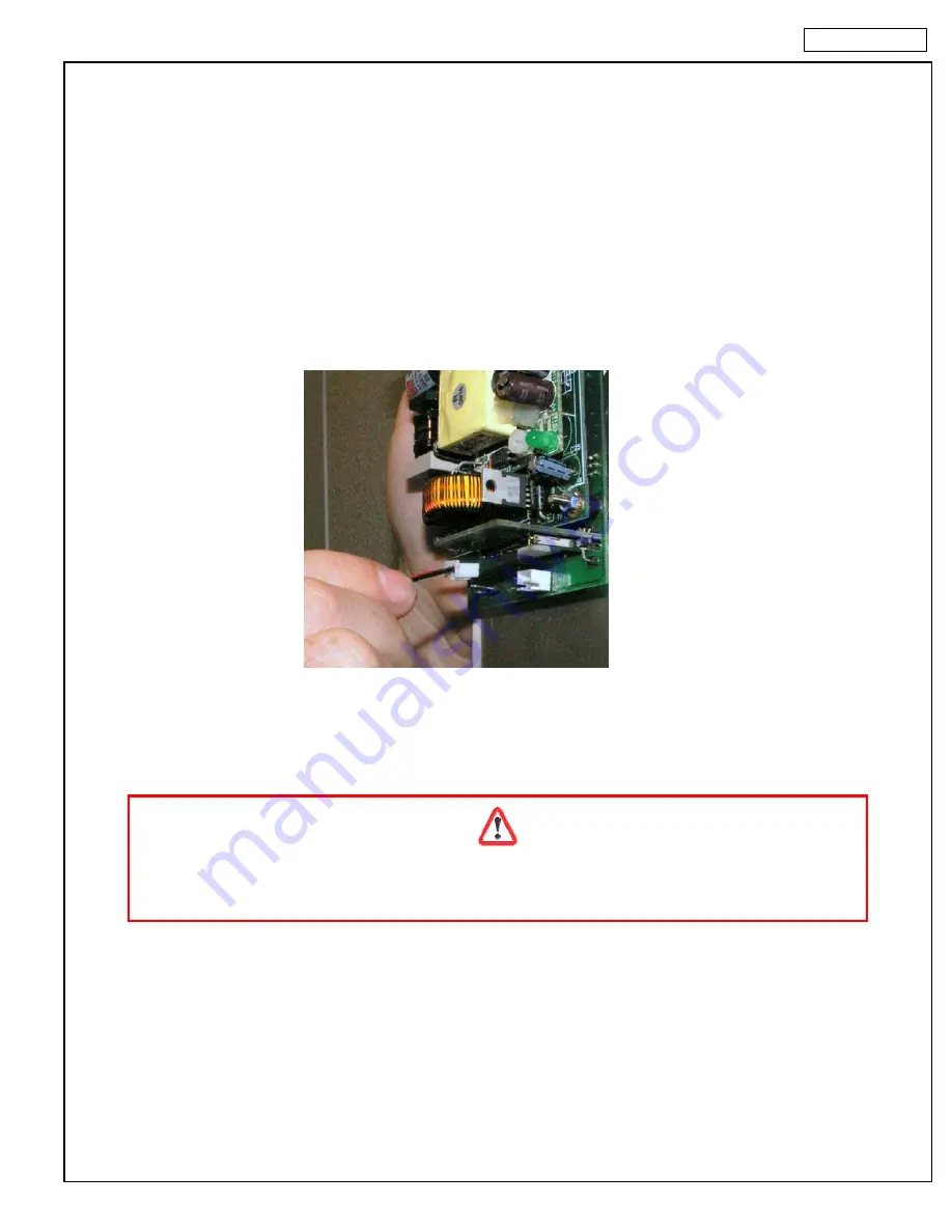
Connect The Battery Pack
To prevent battery drainage and failure, WIMS 200 systems are shipped with the battery pack disconnected
form the electronic board. Connect the battery pack to the electronic board
only when the walk-in cabinet is
ready for use
.
To connect the battery pack, follow the instructions below:
Disconnect the controller from the main power supply (circuit breaker).
Remove the four screws from the faceplate of WIMS 200.
Carefully remove the electronic board.
Locate the battery pack and the white connector.
Insert the white connector into the corresponding connector at the electronic board.
Reinstall the electronic board and power up the controller.
Enter the programming mode to set the current date and time (see Chapter 3).
10.2.
Replace The Batteries
When replacing the batteries use only pre-charged rechargeable 1.2V AA Ni-Mh batteries!
Using any other type of batteries will void the warranty!
WIMS 200 uses three AA Ni-Mh pre-charged rechargeable batteries. These batteries should last for many years.
However, if need be, these batteries can be replaced. To replace the batteries do the following:
Disconnect controller from the main power supply (circuit breaker).
Remove the four screws from the faceplate of WIMS 200.
Carefully remove the electronic board.
Locate and remove the battery pack.
Replace the batteries with new
1.2V AA pre-charged rechargeable Ni-Mh batteries
.
Reinstall the electronic board and power up the controller.
Enter the programming mode to set the current date and time (see Chapter 3).
Summary of Contents for Walk-in Monitoring System 200
Page 6: ...CONTROLLER 6 2 Controller...
Page 32: ...ELECTRICAL DIAGRAMS 32 13 Electrical Diagram 13 1 Wiring Diagram...
Page 33: ...ELECTRICAL DIAGRAMS 33...
Page 34: ...ELECTRICAL DIAGRAMS 34...
Page 35: ...ELECTRICAL DIAGRAMS 35...
Page 36: ...ELECTRICAL DIAGRAMS 36 13 2 PC Connection Wiring Diagram...


