background image


SD Video Recorder                                                                                                                     


  50 - 


Mark 

Color 

Description 

VO 

BNC Connector, in Yellow 

Video output 

AO 

RCA Connector, in White 

Audio output 

12V 

Power output for 12 VDC, Maximum current 1A) 

GND 

DC Connector, in Black 

Ground 


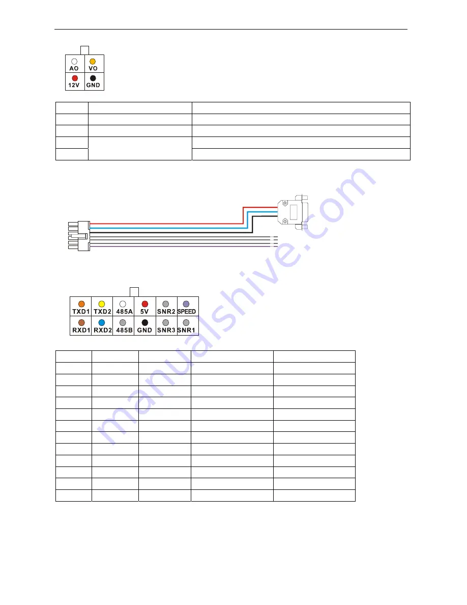
7.3 Sensor Harness 


Pin No. 

Description  Color 

Description 

GPS Connector 

TXD1 

Vacant 

TXD, COM1, (GPS) 


TXD2 

Vacant 

TXD, COM2 


485A 

Vacant 

RS485 A, (PTZ) 


5.0V 

Red 

+5 VDC 

Pin 9 

SNR2 

Grey 

Sensor 2 


SPEED 

Violet 

Speed sensor 


RXD1 

Vacant


RXD, COM1, (GPS) 


RXD2 

Blue 

RXD, COM2 

Pin 3 

485B 

Vacant 

RX485 B, (PTZ) 


10 

GND 

Black 

Ground 

Pin 5 

11 

SNR3 

Grey 

Sensor 3 


12 

SNR1 

Grey 

Sensor 1 


3)


GPS connector (RS232 COM1) 

Summary of Contents for SD4mX

Page 1: ...Now Without Monthly Cellular Service Charges Managed Solution Fees American Bus Video Inc sales AmericanBusVideo com 770 263 8118 DriverSafetyCameras com FleetDriverRiskManagement com 25 Years of Fle...

Page 2: ...1 Call for qualified maintenance man to repair when needed 12 The device can only be installed horizontally Installed vertically or out of the horizontal could hurt person or damage the device or and...

Page 3: ...16 5 BASIC OPERATION AND MENU SYSTEM 17 5 1 SD CARD FORMATTING 17 5 2 CHOOSE RECORDING MODE 18 5 3 FILE LENGTH 19 5 4 RECORDING QUALITY 19 5 5 START RECORDING 21 5 6 PLAYBACK OPTION 22 5 6 1 Playback...

Page 4: ...h to turn on off the DVR system 37 6 8 2 Turn On Off DVR System Automatically 38 6 9 USE PTZ 39 6 9 1 PTZ Control 39 6 9 2 Rename the camera 40 6 9 3 Video Adjustment 40 6 10 GPS SETTING OPTION 41 6 1...

Page 5: ...undesired operation Product Description The SDVR unit consists of the following major components Standard Components and Features x Extruded aluminum case the case is anodized in cobalt blue x Front a...

Page 6: ...r battery voltage after Ignition off and auto into sleep mode when voltage is bellow specified level Recording mode x Continuous record x Support schedule recording x Support alarm recording x Support...

Page 7: ...s On Blinking SDVR is on running Blinking with RUN by turns Blinking with PWR by turns Ignition is not enabled and SDVR is OFF Blinking together with RUN Blinking together with PWR Ignition sense is n...

Page 8: ...put 3 including audio input 1 video input 1 and power output for camera 3 AV input 4 including audio input 1 video input 1 and power output for camera 4 AV output including audio output video output a...

Page 9: ...urrent menu If you modify something in the menu recorder will prompt a window to ask you to save or cancel your modification 4 Press VIDEO to toggle among different video channel 5 Press AUDIO to togg...

Page 10: ...of the tamper proof case in the right place inside the vehicle 2 Put the DVR system inside the bottom cover and load a SD Card NOTE The lock jumper of SD Card should be in OFF position Kingston Class...

Page 11: ...V for the DVR The DVR may be damaged if the voltage comes too high And the DVR may not work if the voltage comes too low 3 Power of the DVR should be supplied by the car battery 4 Power consumption of...

Page 12: ...Recorder 12 3 3 Camera Connection Two different kinds of Audio Video Cables for option 1 4 pin threaded cable with male connector for each camera Pin 1 12V power Pin 2 GND Pin 3 Audio Input Pin 4 Vid...

Page 13: ...cable The DVR system will provide stable 12V DC power to each camera and record video and audio if the camera is with microphone built in This type of connection cable is highly recommended It saves...

Page 14: ...SD Video Recorder 14 3 4 Sensor Harness Connection GPS Connection Option PIN Description 3 RXD2 Data receive 5 GND Ground 9 5V DC Power output...

Page 15: ...SD Video Recorder 15 3 5 Event Button and Cable Connection Option...

Page 16: ...SD Video Recorder 16 4 Main System Overview...

Page 17: ...ur PC PationManager which can be downloaded from internet free of charge is recommended to be used for fast formatting and batch processing 2 If the SD Card is never formatted or the file system is co...

Page 18: ...rding Mode Two recording modes for option Composite Mode and Separate Mode The defaulted recording mode is Separate Mode You can change to Composite Mode by steps given as below if needed a Press MENU...

Page 19: ...ins 30mins 45mins and 60mins The defaulted file length is 5 minutes The maximum file length is 60 minutes 5 4 Recording Quality Press MENU to enter the DVR system menu choose RECORD and enter its sub...

Page 20: ...if you are recording 4 channel video synchronously Quality Resolution Still Image Bitrate Bit s Movement Image Bitrate Bit s Audio Bitrate Bit s File Capacity BASIC 2 3 D1 PAL 480 384 NTSC 480 320 350...

Page 21: ...up at the top left corner of each camera channel In Separate Mode by default the DVR system will record all channels If you want to record a specific channel s use or number key 1 2 3 4 to select the...

Page 22: ...yback the latest file of first camera channel ch 01 Use or number key 1 2 3 4 to select a specific camera channel and press PLAY to playback The play status is indicated by a green triangle on the top...

Page 23: ...ories will be listed for option The directories will be listed by order of the date and hour To take 2011 04 27_14 for an example it means this directory contains all files recorded from 14 00 00 to 1...

Page 24: ...files 5 7 File Backup a Insert an USB flash drive into USB port on front panel of the DVR system b Press MENU by remote choose STORAGE and press MENU to enter its sub menu c Go to SEARCH BY TIME and...

Page 25: ...l be enabled if it is connected to the HIGH level 12V If you need the sensor alarm 3 to be triggered by LOW level GND you should set this to be LOW If you set the TOGGLE as CH 01 the screen will toggl...

Page 26: ...ent post recording in modes of alarm recording and motion detection recording That means the DVR system will keep recording for scheduled time after alarm recording completes 1 Press MENU by remote to...

Page 27: ...he RECORD as ON press OK to save and exit When motion detection is triggered you will see a yellow dot flashing at the upper right corner 5 9 3 Set Motion Sensitivity Press MENU to enter the DVR syste...

Page 28: ...ts sub menu go to VIDEO LOST and set the buzzer as ON press OK to save and exit 6 1 Schedule Recording Press MENU by remote to enter the DVR system menu choose RECORD and press MENU to enter its sub m...

Page 29: ...and Time 6 3 1 Set Date Display Format Press MENU to enter the DVR system menu choose SYSTEM and press MENU to enter its sub men go to TIME ZONE and set the DATE FORMAT YY MM DD MM DD YY or DD MM YY 6...

Page 30: ...onfiguration modifications will be save to internal flash of the DVR system 2 User Config Reset If some improper modifications have been done and you would like to reset to the previous configuration...

Page 31: ...with no password To set the user name and password 1 Press MENU to enter the DVR system menu choose SYSTEM and press MENU to enter its sub menu set the LOGIN VERIFY to be YES press OK to save and exi...

Page 32: ...Pass and Pass Confirm press OK or MENU to save and exit 6 6 Network Setting The system supports both Static IP and Dynamic IP Press MENU to enter the DVR system menu choose NETWORK and press MENU to...

Page 33: ...e the IP address automatically 3 HOST NAME is used for setting the DVR system s name 6 7 MOTOR 6 7 1 Set LICENSE ID and LINE Press MENU to enter DVR system menu choose MOTOR and press MENU to enter it...

Page 34: ...2 3 485A Vacant RS485 A PTZ 4 5 0V Red 5 VDC Pin 9 5 SNR2 Grey Sensor 2 6 SPEED Violet Speed sensor 7 RXD1 Vacant RXD COM1 GPS 8 RXD2 Blue RXD COM2 Pin 3 9 485B Vacant RX485 B PTZ 10 GND Black Ground...

Page 35: ...sub menu set the SPEED CHECK as From GPS and press OK to save and exit 3 The speed will be displayed on the left bottom of the monitor If you need the speed to be MPH other than KM H please select mi...

Page 36: ...r 2 If the speedometer already has a signal output wire showed as SIG output in the following diagram you can connect Speed sensor input wire to the SIG output wire directly 3 If the speedometer does...

Page 37: ...n it s not easy to pulse number by the calculation on the paper In this case you can choose the menu item 10 Vehicle Setup then set the Pulse No to be 0 Then you drive the car for one kilometer The nu...

Page 38: ...If the number is set to 0 the camera and DVR system shut off right after the ignition switch if in the OFF position 4 If the vehicle is using low level as ignition signal you need to set the IGNITION...

Page 39: ...OWER ON and POWER OFF time as 00 00 by defaulted 6 9 Use PTZ 6 9 1 PTZ Control 1 Connect the RS485 of DVR system to PTZ communication port 2 Press MENU to enter DVR system menu choose LIVE and press M...

Page 40: ...choose LIVE to enter its sub menu go to CAMERA TITLE and press MENU to enter rename each camera by press MENU to get the TEXT INPUT dialog box 3 After pressing OK to save the change the new camera nam...

Page 41: ...will show GPS NONE b GPS BURNIN can be set as ON or OFF If it is set to be ON the GPS coordinate will be shown on the screen if it is set to be OFF the coordinate will be hided c GPS TIME SYNC can be...

Page 42: ...aulted 15s for an example the alarm recording will last for 15 minutes since the Event Button is pressed then stop 4 If you use Separate Mode for recording press MENU to enter the DVR system menu choo...

Page 43: ...b Press the Event button the LED will flash in red and you will hear buzzer if you set the BEEP as ON it means alarm recording is triggered c The alarm recording is recorded in the log file Please us...

Page 44: ...se SYSTEM and press MENU to enter its sub menu 4 Choose SYSTEM INFO go to APP UPDATE and press MENU to get ready for system update 5 Press YES to exit the current program and continue with the upgrade...

Page 45: ...while updating 7 Upgrade Success will be shown up to remind you when update is successful press MENU by remote to restart the application 6 13 Using Wi Fi Module Option 1 Debug the Wi Fi module on PC...

Page 46: ...PC is Win 7 or Vista please choose If the operation system is WinXP please choose then go with NEXT to finish the installation c After that you will find on your desktop Double click this icon to run...

Page 47: ...of your password in hex format You can look up the ascii code of your password in the ascii table Appendix A For an example if your password is hello you should input 68656c6c6f in Key1 then press Nex...

Page 48: ...You will get three icons of ViewPro AVPlayer and Record Calculator on your PC desktop ViewPro is used for live view file download set DVR remotely etc AVPlayer is used for files playback b Run the Vi...

Page 49: ...ntrol the power GND BLACK of power supply you can connect to Battery 7 2 Video Audio Input Output Cable 1 Video Audio Input Cable Viewed from crimp side Mark Color Description VI BNC Connector in Yell...

Page 50: ...Ground 7 3 Sensor Harness Pin No Description Color Description GPS Connector 1 TXD1 Vacant TXD COM1 GPS 2 TXD2 Vacant TXD COM2 3 485A Vacant RS485 A PTZ 4 5 0V Red 5 VDC Pin 9 5 SNR2 Grey Sensor 2 6...

Page 51: ...SD Video Recorder 51 PIN Description 3 RXD2 Data receive 5 GND Ground 9 5V DC Power output...

Page 52: ...OMPRESSION G 711 STORAGE SD card external USB device memory stick or hard drive STORAGE FILE FORMAT AVI SENSORS 1 speed sensor 1 ignition sensor 3 sensors for brake return etc COM PORT 2 RS232 port 1...

Page 53: ...four channel SDVR 5 AV output cable 1 pc 6 Signal cables 1 pc 7 Power cable 1 pc 8 Remote Controller 1 pc 9 Fuse box 1 pc 10 1 5A fuse 2 pcs 11 Screws 4 pcs 12 User s Manual 1 pc Options Item Descript...

Page 54: ...se move the picks to the non write protected 4 Q What is a high level what is low level A Generally there are two electrical levels in the car the power and the ground Automotive power voltage with 12...

Page 55: ...ns most of USB disks sold on the market are the products of the USB1 1 Their speed can not meet the data rate of the requirements of the DVR Please replace USB2 0 products for the faster speed 10 Q Do...

Page 56: ...can t display all the images images on the right and below the video will be cut off 14 Q How to upgrade the SD DVR program A 1 Copy the update package Suffix tar files to the root directory of SD ca...

Page 57: ...ts advantages are high definition storage space saving and convenient playing 18 Q How long will my SD card of 32GB record A we have provided recording volume calculator software on the accessory CD w...

Page 58: ...is the highest sensitivity the first level is the lowest sensitivity Second make sure that if your camera system PAL system or NTSC system match the stroboscopic lighting devices such as fluorescent l...

Reviews: