background image

Alvarado Manufacturing Company, Inc. 

12660 Colony Street, Chino, CA 91710 

Phone: +1 (909) 591-8431 

Fax: +1 (909) 628-1403 

[email protected] 

www.alvaradomfg.com

PUD3667R1-6

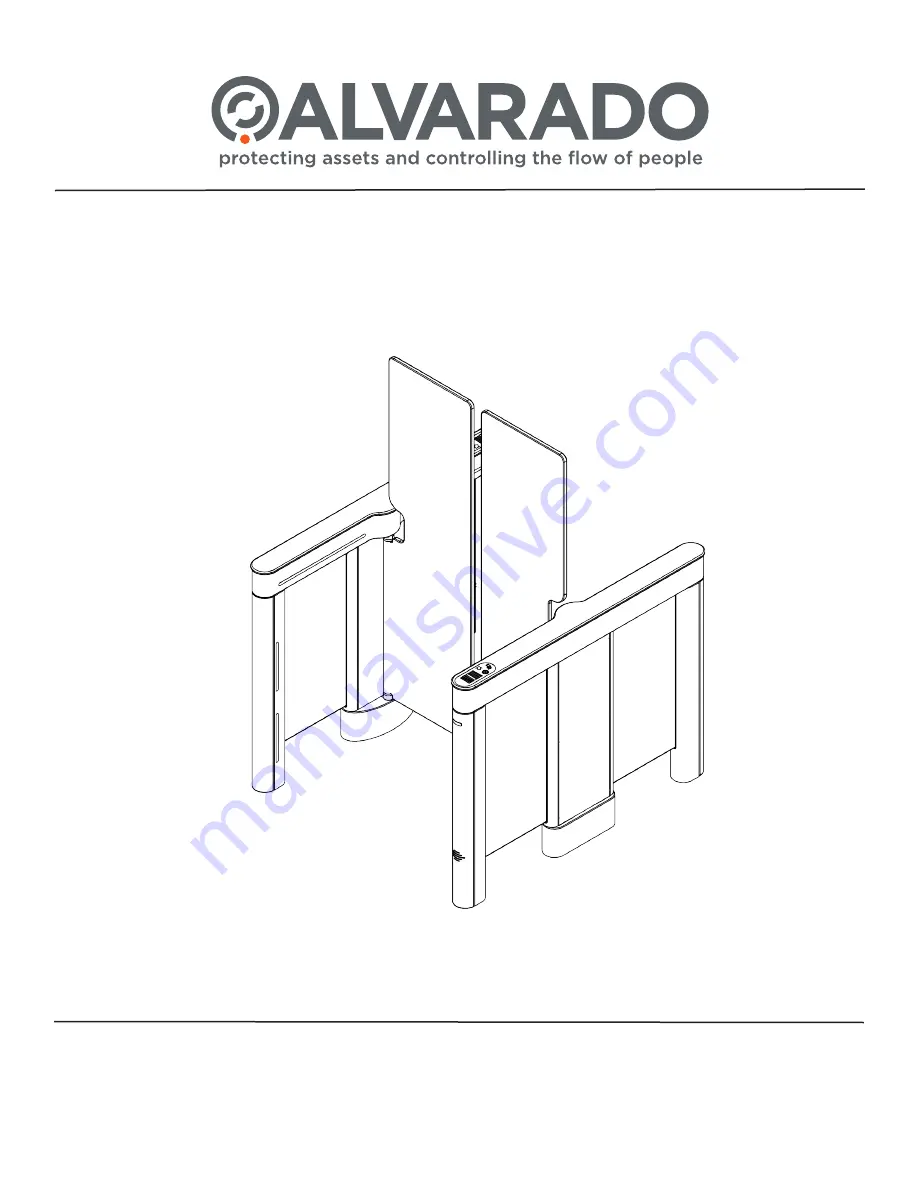
SUPERVISOR 5000 

(SU5000)

Optical Turnstile with Bi-directional Motorized Barriers

Installation Instructions

Summary of Contents for SU5000

Page 1: ...2660 Colony Street Chino CA 91710 Phone 1 909 591 8431 Fax 1 909 628 1403 support alvaradomfg com www alvaradomfg com PUD3667R1 6 SUPERVISOR 5000 SU5000 Optical Turnstile with Bi directional Motorized...

Page 2: ...on 14 Internal Card Reader Installation 15 Wiring Instructions 16 Primary Power 16 Crossover Cable Connection 16 I O Control Board 13 0328 Rev F 17 Configuring Passage Modes 19 Ethernet Communication...

Page 3: ...damaged turnstile Closely follow the handling instructions for moving or lifting the turnstile during installation Power off the turnstile before connecting or disconnecting any communication or power...

Page 4: ...ginning installation If parts are missing and or damaged please contact Alvarado End covers ship taped to the turnstile cabinets Barrier height and width may vary Single Lane Parts List Concrete Ancho...

Page 5: ...rossover Cable Qty 1 End covers ship taped to the turnstile cabinets Barrier height and width may vary Center Cabinet Parts List Per Center Cabinet Concrete Anchor Package Hardware Parts List cont x 2...

Page 6: ...the lid below the user status display Center cabinets contain both master and slave components Center cabinets are extension cabinets used in multi lane applications An unlimited number of center cabi...

Page 7: ...ormation on I O interfacing is provided later in this manual For select projects a TCP IP interface is available This interface allows a third party access system to communicate to from the SU5000 usi...

Page 8: ...into consideration when selecting the installation location A level solid concrete pad with a minimum thickness of 4 102mm Use full sweep electrical conduit underneath the floor Three separate conduit...

Page 9: ...rements Peak power consumption is 300W per lane with all options installed Operational Voltage Primary power is stepped down and rectified for low voltage 24 VDC 12 VDC and 5 VDC operation Fuse 2 5A s...

Page 10: ...rally only mullion sized card readers can be installed inside the cabinet The physical dimensions of the card reader cannot exceed 1 00 H x 1 90 W x 6 50 D 25mm x 48mm x 165mm All personnel that will...

Page 11: ...and two 2 motor shims located in the center cabinet if applicable 1 Remove each shim after the cabinet panel has been removed by pulling firmly on the orange pull tab Figure 7 IMPORTANT Pre Installati...

Page 12: ...e in the marked location 3 Determine how the primary power and access control wiring will be routed to the master and or center cabinet Most commonly the wiring is run into the baseplate through one o...

Page 13: ...are each cabinet with respect to the floor and other cabinets A Measure the distance from the inside wall of one cabinet top channel to the inside wall of the other cabinet top channel on both the ent...

Page 14: ...nsert seven 7 3 8 x 2 1 2 anchor bolts and flat washers 9 Using a socket wrench and 9 16 socket provisionally snug the anchors Do not fully tighten them yet The anchors are not torqued to specificatio...

Page 15: ...ert and tighten four 4 Phillips head mounting screws Figure 14 7 Route the output cable through the turnstile and connect to your access control system Figure 15A 15B Output cable must be routed down...

Page 16: ...ster cabinet Figure 18 4 Repeat Steps 1 3 for the slave cabinet Wiring Instructions IMPORTANT 110VAC and 220VAC primary power must be hard wired in place It is strongly recommended that a licensed ele...

Page 17: ...momentary dry contacts MDC and sustained dry contacts SDC All input signals must be normally open N O voltage free dry contacts with the exception of the fire alarm input which can be configured via...

Page 18: ...ssage is completed 9 EXTACC Good Card Exit MDC Opens the turnstile for one authorized passage until passage occurs or timeout 10 EXTALRX Unauthorized Presence Exit MDC An output occurs when there is e...

Page 19: ...Key Control If this option has been ordered for your turnstiles two 3 position key switches are installed on the turnstile Turning the key to one of the three positions allows each turnstile directio...

Page 20: ...ate the ENTPAS and GND terminals 2 Using a wire jumper connect the ENTPAS and GND terminals Figure 21 Exit Direction 1 Locate the EXTPAS and GND terminals 2 Use a wire jumper to connect the EXTPAS and...

Page 21: ...d unattached to the turnstile The clamp bars and hardware are packaged in the box labeled HARDWARE ENCLOSED This installation requires two people One person will need to hold the barrier while the oth...

Page 22: ...does not wiggle Figure 25 3 Once the barriers have been installed check that they are level and lined up properly in the Home position If the barriers do not line up in the Home position the cabinets...

Page 23: ...stment after installation Refer to Appendix A on Page 32 for instructions on setting the barrier Home position The keys to power the turnstile ON OFF are packaged in the hardware box that was shipped...

Page 24: ...Unsecured Side Unauthorized Entry shown Authorized Entry shown Secured Side Unsecured Side Testing Turnstile Functionality TEST PROCEDURE TURNSTILE RESPONSE Enter the turnstile without authorization...

Page 25: ...ng the turnstile Barriers close after passage completion Enter the turnstile User Status Light red icon is illuminated Open Closed Status Light is red No alarms sound when standing in the turnstile Ba...

Page 26: ...hown in Figure 28 Turning the key to one of three positions overrides all existing settings placing the turnstile in Controlled Passage mode Free Passage mode or No Passage mode depending on the orien...

Page 27: ...ng CMD in the Search programs and files field 5 Enter the following command ping XXX XXX XXX XXX where XXX XXX XXX XXX is the IP address of the turnstile Figure 29 6 A successful ping will result in t...

Page 28: ...ll end cabinet lids 1 Lower the lid onto the cabinet housing Figure 32 Do not force the lid into place Doing so may damage the lid 2 Insert the M4 stubby Allen wrench into the cam latch assembly locat...

Page 29: ...e cabinet panel to the cabinet Figure 33 3 Repeat steps 1 and 2 to install the remaining cabinet panel s Fig 33 Cabinet Panel Installation Base Cover Installation 1 Place the base covers in position T...

Page 30: ...4 Barrier Alignment Barriers are properly aligned in both the open and closed positions Barriers aligned in the Home position 5 Attachment Barriers cabinet lids end covers and base covers are securely...

Page 31: ...s Blocked Sensor auditory alarms sounds after 15 seconds default Wire or cable blocking sensors Check for a stray wire or cable in front of the transmit and receive operational sensors horizontal arra...

Page 32: ...in test mode Figure A1 3 Move the barrier a couple of inches in both directions and then place it in the home position Figure A3 4 Press the Home button to set 5 Press the Test Mode button for two sec...

Page 33: ...CONDUIT THRU ALL THRU ALL 1 9 1 3 1 3 2X 2X 2X 2X 2X 3X 6 6 15 15 9 7 23 4 23 4 6 3 3 3 2 6 0 3 3 6 3 9 48 33 33 23 0 18 594 594 160 84 66 84 160 23 Plan View Elevation View Footprint 17 0 36 0 43 0 4...

Page 34: ...tructions Page 34 For assistance support alvaradomfg com 1 909 591 8431 PUD3667R1 6 Appendix C 28 36 Baseplate Dimensions 40 8 1036 5 52 5 1333 5 Fig C1 28 Baseplate Dimensions 48 8 1239 7 52 5 1333 5...

Page 35: ...ded Wire gauge recommendations for 30 50 and 100 ft runs are provided on Page 37 If your installation requires runs beyond 100 ft ensure wire gauge is appropriate and in compliance with local electric...

Page 36: ...onduit holes on the enclosure Figure D3 4 Locate the pre installed primary power terminal block Figure D3 There is one primary power terminal block per enclosure 5 Attach each primary power wire to th...

Page 37: ...minal block as shown in Figure D5 13 Repeat Steps 9 12 for additional power supplies and turnstiles Fig D4 Power Supply Output Terminal Block Fig D5 Turnstile Power Terminal Block The 24VDC V and GND...

Page 38: ...alvaradomfg com 1 909 591 8431 PUD3667R1 6 LANE 1 MASTER CABINET CENTER CABINET SLAVE CABINET CENTER CABINET LANE 2 LANE 3 110VAC 220VAC INPUT POWER SUPPLY ENCLOSURE 24VDC OUTPUT TO CIRCUIT BREAKER Ex...

Page 39: ...ation Instructions PUD3667R1 6 For assistance support alvaradomfg com 1 909 591 8431 Page 39 24VDC CONDUIT HOLES 110 220VAC CONDUIT HOLE Power Supply Enclosure Dimensions 15 80 401 4 9 50 241 3 6 23 1...

Page 40: ...uration Master Cabinet LANE 1 LANE 2 Slave Cabinet Center Cabinet Three Lane Configuration Master Cabinet Slave Cabinet Center Cabinet Center Cabinet Symbology Description Conduit Size Primary Power 3...

Page 41: ...ssover Cable Connection Diagrams MASTER SLAVE Master Cabinet Slave Cabinet SLAVE SLAVE MASTER MASTER Master Cabinet Center Cabinet Slave Cabinet LANE 1 LANE 2 SLAVE SLAVE SLAVE MASTER MASTER MASTER Ma...

Page 42: ...es Added instructions for leveling cabinets and checking barriers for straightness 1 3 06 09 15 A Flores Added Appendix D External DC Power Supply Installation Instructions and Appendix E Multi Lane C...

Page 43: ...Installation Instructions support alvaradomfg com 1 909 591 8431 www alvaradomfg com Page 43 This page intentionally left blank...

Page 44: ......

Reviews: