background image

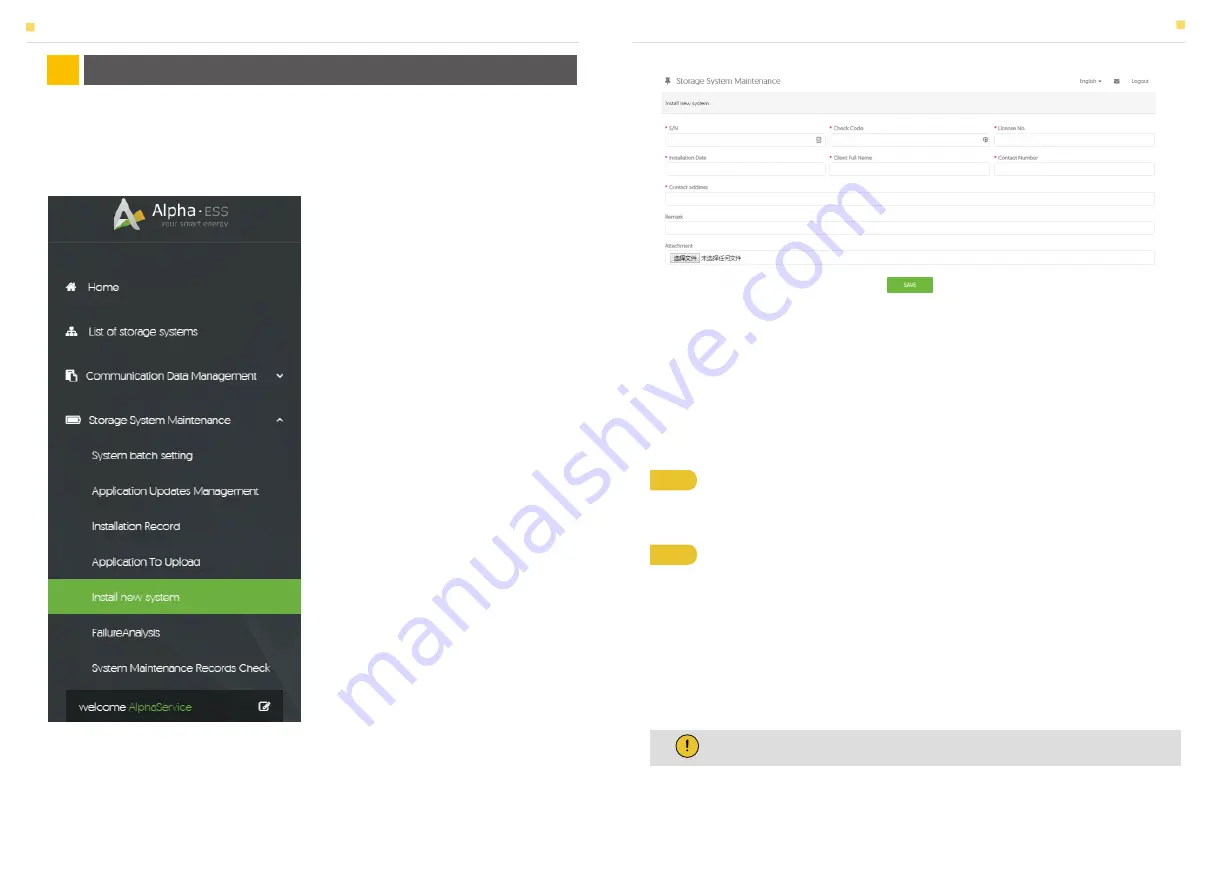
Installers who haven't registered yet need to click “Register” to visit the registration page. 

Please refer to “AlphaCloud Online Monitoring Webserver Installers User Manual”, which 

you can get from AlphaESS sales along with your personal license number.

Enter the system S/N, check code, license, installation date, client name, contact number, 

contact address, and click the save button. The red* marks indicate that the specific info 

is necessary there. Click the Browse button to select an attachment you want to add.

Some of the system settings must be carried in the installer monitoring. To do this, 

follow the steps below:

Log in to your installer account and choose 

Storage System Maintenance> "Install new 

system" to register a new system at AlphaESS.

Step 1 

 Please login in the installer account, click the list of storage systems and 

enter the SN.

Step 2 

 After selecting the correct system, enter System Setup interface. Enter in 

the "Basic Information" and input below information:

- Address,

- Zip code,

- Contact name,

- E-Mail address,

- Currencies and

- Telephone number.

6.1 System Setup in Monitoring

6.1.1 Basic Information

ONLINE MONITORING

06

ONLINE MONITORING

ONLINE MONITORING

Note: 

Do not forget to click “Save” button!

46

47

Summary of Contents for SMILE5 AU

Page 1: ... 63225 Langen Hessen Alpha ESS Australia Pty Ltd 61 402 500 520 Sales 61 1300 968 933 Technical Support australia alpha ess com www alpha ess com au Suite 1 Level 1 530 Botany Road Alexandria NSW 2015 Alpha ESS Italy S r l 39 599 239 50 info alpha ess it www alpha ess it Via Loda 17 41013 Castelfranco Emilia MO Alpha ESS Korea Co Ltd 82 64 721 2004 korea alpha ess com 2F 19 4 Nohyeong 11 gil Jeju ...

Page 2: ...stallation 2 2 1 Battery Installation 2 2 2 Inverter Installation 2 2 3 Single Line Diagram 2 3 Power Meter 2 3 1 Meter ADL 3000 If Applicable 2 3 2 Meter SM60A If Applicable 2 3 3 ACR10R Meter If Applicable 2 3 4 Backup Box If Applicable 2 3 5 Meter Setting 3 1 Switch On 3 2 Switch Off 3 3 Emergency Procedure 3 3 1 Emergency Handling Plan 3 3 2 Hazards 3 3 3 Fire 1 4 General Precautions 1 5 Parts...

Page 3: ...al and Equipment Inspection 7 2 Notes 1 1 System Introduction INTRODUCTION 01 INTRODUCTION AlphaESS SMILE5 incl SMILE5 BAT and SMILE INV can be applied in DC coupled systems mostly new installation AC coupled systems mostly retrofit and Hybrid coupled systems mostly retrofit and PV capacity increase as the following scheme show Figure 1 DC coupled Storage System Scheme Figure 2 AC coupled Storage ...

Page 4: ...er before an installer works on the equipment 1 2 2 Operator Requirements The operators should get a professional qualification or get trained The operators should be familiar with the whole storage system including compositions and working principles of the system The operators should be familiar with the Product Instruction During maintenance the maintainer is not allowed to operate any equipmen...

Page 5: ...onductors Do not open the inverter and battery Do not wipe the system with damp cloth Have the system installed and commissioned by qualified people with the appropriate skills only Prior to performing any work on the inverter or the battery pack disconnect the inverter from all voltage sources as described in this document WARNING Risk of chemical burns from electrolyte or toxic gases During stan...

Page 6: ... 1x Warranty Card WiFi Module Optional 1x Wall Bracke 1x Position Plate 4x M6 Nuts 2x M4 Nuts 4x M8 60 2x PV Connector 1x Meter 1x SM60A or 1x ADL3000 or 1x ACR10R Object 1 2 3 4 5 Description Hybrid Inverter with Cable Box EMS Display Screen Cable Box Part of Inverter SMILE5 BAT Battery 1 SMILE5 BAT Battery 2 SMILE5 INV 6x M8 60 6x M6 Gasket 4x RJ 45 plugs Battery Communication Cable 6x M5 10 2x ...

Page 7: ...overs Front View Dry Contact Relay Meter CAN Inverter Debug Communication Port Net Wire Connection Port Battery Communication Port External Expansion Port Or External Dispatching Port Power Dispatching Port for Australia Meter Communication Port External Device Control Interface Object PV1 PV2 Object GRID BACKUP Description PV Connector Description Grid Wiring Outlet Backup Wiring Outlet Cable Box...

Page 8: ...g painting scratch caused by rubbing inside packaging during shipping A claim should be made directly to shipping or insurance company in this case as soon as the container packaging is unloaded and such damage is identified Failure to follow any all of the user manual the installation guide and the maintenance regulations Improper use or misuse of the device Insufficient ventilation of the device...

Page 9: ...nt fixation of the mounting plates 2 2 Installation 2 2 1 Battery Installation Step 1 Remove the battery and inverter from the packaging box Step 2 Connect the power cable at the top which are included in the parts list of SMILE5 BAT M5 10 Screws Figure 13 Battery Installation Drill Holes Step 5 Remove the WiFi panel on the top and install the WiFi module tool T20 screwdriver torque 1 6Nm Please r...

Page 10: ... Second Battery Installation M8 60 14 15 Figure 17 Inverter Mounting Panel Installation Figure 18 Inverter Installation Inverter Mounting Panel Step 7 To assemble the second and all other battery repeat steps 2 to 5 respectively Step 8 Remove the inverter mounting plate and bracket and connect them using the M4 nuts as shown above Check carefully if everything is tight INDOOR Step 9 Drill the corr...

Page 11: ...e and the BMS commu nication cable to the corresponding COM ports All of the three cables are regular net cables type 568B You can use the communication cable provided in the accessory parts of one SMILE5 BAT as the BMS communication cable The following figure shows the type 568B line sequence Step 13 Open the battery front covers Connect the BMS communication cable of the cable box from Step 11 t...

Page 12: ... mode and close the cover again 1 If there is only one BAT the DIP switch of this BAT must be set as the following 2 If there are two or more than two BATs the DIP switch of the BATs must be set as the following Step 15 Connect the power cables of the bottom battery from Step 2 to the side terminals of the top battery Make sure that red connects to red and black connects to black Figure 23 Wiring ...

Page 13: ... for the first two batteries including the DIP setting on the last module Figure 26 Increase the Battery Modules Figure 28 AC coupled system Figure 29 Hybrid coupled system 2 2 3 Single Line Diagram The single line diagrams of DC AC and Hybrid coupled system are as below Figure 27 DC coupled system INSTALLATION INSTALLATION Note Recommended external PV circuit breaker rating is not less than 25A N...

Page 14: ... with or without CT SM60A single phase meter Backup Box three single phase meter Contain off grid switching and load management ACR10R Three phase CT electric meter LOAD LOAD LOAD PE BACK UP GRID G L N G L N LAN1 LAN2 BAT DRMs METER PE BACK UP GRID G L N G L N LAN1 LAN2 BAT DRMs METER PE BACK UP GRID G L N G L N LAN1 LAN2 BAT DRMs METER LOAD PE BACK UP GRID G L N G L N LAN1 LAN2 BAT DRMs METER INS...

Page 15: ...ower meter PIN 7 8 to the meter port of the cable box PIN 3 6 using the RJ45 cable ADL 3000 three phase connection with CT without meter plug if applicable Figure 36 ADL 3000 three phase Connect with CT without Meter plug ADL 3000 three phase connection with CT with meter plug if applicable Figure 37 ADL 3000 three phase Connect with CT with Meter plug Figure 38 Two Meter Connect with Meter Plug F...

Page 16: ... arrow in CT should point away from the grid to the energy storage system If the ADL3000 meter with CT is used as a PV meter in AC or hybrid coupled system the direction of arrow in CT should point away from the PV inverter to the energy storage system For AC Hybrid system there are two meter needed Note Connect the power meter PIN 5 6 to the meter port of the cable box PIN 3 6 using the RJ45 cabl...

Page 17: ...V INV_L2 PV INV_L3 PV INV_N L N L GRID_PE PV INV_PE PE PE PE COM patch cable meter patch cable for backup box Meter Port patch cable RCD patch cable Backup Box Connect to SMILE5 three phase grid in house GRID_N GRID_L3 GRID_L2 GRID_L1 Storion S5 ECO ES5 SMILE5 PV INV BACK AC N L L N PV PV Bat meter LOAD3 LOAD2 LOAD1 GRID DSP_BackupBox BAK_N AC_N LOAD_N BAK_L3 AC_L3 LOAD_L3 BAK_L2 AC_L2 LOAD_L2 BAK...

Page 18: ...o enter the above interface and press the up and down arrow keys to enter the password 0001 Step 5 Click the Enter button again to enter the address interface Step 7 Click the Enter button and the address setting is completed Step 6 Click the Enter button and press the up and down arrow keys to set the meter address The Grid meter DC AC and Hybrid system address is set to 001 the PV meter AC and H...

Page 19: ...e DC link capacitance inside the battery modules is discharged completely Step 1 Open the outer shell of the cable box Unlock then open the inner cover of the cable box Step 2 Press the power button on all the batteries till the lights turn off Step 3 Turn off the Battery switch Step 4 Turn off the Grid switch Step 5 If backup load is applied turn off the Backup switch Step 6 Turn off the PV switc...

Page 20: ...ly If it is OK return the power supply to find out the reason 3 Please record every detail related to the fault so AlphaESS can analyze and solve the fault Any operation of equipment during a fault is strictly forbidden please contact Alpha as soon as possible 4 As battery cells contains a little Oxygen inside and all cells have got explosion proof valves explosion hardly happens 5 When the indica...

Page 21: ...I1 power P1 voltage U2 current I2 and power P2 4 2 1 Main 4 2 2 Status 4 2 3 History Battery interface displays the real time information of battery side voltage U current I power P residual capacity of Battery SOC the internal environmental temperature Temp UPS interface displays the real time information in this mode voltage U current I power P frequency F Communication interface displays the re...

Page 22: ... the information menu are correct 4 2 4 Setting 4 2 4 1 General Setting Step 1 Click setting and enter the password The installation s password is a four digit password 1111 after four digit password is correctly input you can enter into the main Setting interface administrator permissions Step 3 Click Solar to set the Solar relevant information Step 2 Click Function to enter function setting Step...

Page 23: ...lease set CT meter enable and the relevant ratio Step 14 Set the UPS Reserve SOC it means how much battery energy to reserve for UPS function Step 17 If you use UPS function please set the mute as YES in UPS System interface and the relevant Frequency Step 18 Click System in the setting menu Click Date Time and set up the date and time Step 17 Click Ethernet to set the IP address DHCP mode means t...

Page 24: ...ate Time Setting Interface Step 21 Make sure all the following number is correct Note It is needed to set the following 3 parameters for manual mode IP Address IP address Subnet Mask Subnet mask Default Gateway Default gateway Automatic display one parameter MAC Address display MAC Address Step 3 Please choose Phase as L1 master and press enter Step 5 please repeat Step 1 to 4 to set the other dev...

Page 25: ...you haven t registered please register first following the steps after down loading and installing the app 44 45 Next Connect to the hotspot Router Configuration System Configuration Successfully configured Connect to the hotspot Router Configuration System Configuration Submit On Grid PV Capacity kW Grid Meter CT PV Meter Safety Regulations kW CT Meter Meter OK Runnig information Running informat...

Page 26: ...o add Some of the system settings must be carried in the installer monitoring To do this follow the steps below Log in to your installer account and choose Storage System Maintenance Install new system to register a new system at AlphaESS Step 1 Please login in the installer account click the list of storage systems and enter the SN Step 2 After selecting the correct system enter System Setup inte...

Page 27: ...0s data if you wish 7 1 Maintenance Plan 7 1 1 Operating Environment 7 1 2 Equipment Cleaning 6 1 2 Other Information After the equipment are out of operation Please pay attention to the following notes during maintaining process 7 2 Notes ROUTINE MAINTENANCE 07 Every six month Carefully observe whether the battery system equipment is inefficient or damaged When the system is running listen to any...

Reviews: