background image


COMMISSIONING 

86 

9.5.2.


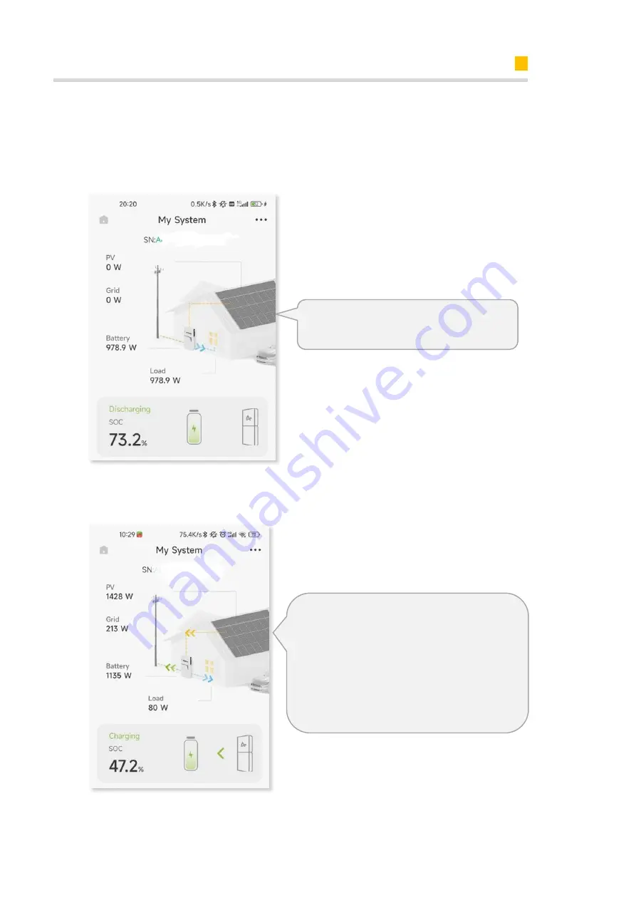
Check the PV Generation and Discharging Function of the Product 

Step1:

  Please  switch  off  the  PV  switch  on  the  energy  storage  inverter  and  the  AC 

breaker on the PV inverter if there is any. Switch on some larger loads to see the battery 
discharging status. 


Step  2:

  Please  switch  on  the  PV  switch  on  the  energy  storage  inverter  and  the  AC 

breaker on the PV inverter if there is any. Check the running status of the system.  


The relative  value should be like this: 

Load = GRID


+


Battery 

The relative  value should be like this: 

Load = PV


±


GRID


±


Battery


±:


charging: - ; discharging: 

+


PV arrow 

should be as the picture shows.


±

>>

absorbing from grid: +; 


<< 

feed-in to grid:-


If  not  correct,  please  check  the  CT  or  meter  installed 

direction on PV side 

Summary of Contents for ES-Alpha-Smile 5-10KWH-v2

Page 1: ...V01 INSTALLATION OPERATION MAINTENANCE MANUAL OF SMILE5 ENERGY STORAGE SYSTEM ESS ...

Page 2: ......

Page 3: ...nt is believed to be accurate and reliable The information and recommendations in this document do not constitute commitments or warranties in the form of assignments The information in this document is subject to change without notice You may refer to the Alpha Cloud Platform https cloud alphaess com for the most updated version All company and brand products and service names are trademarks or r...

Page 4: ...s under the copyright of Alpha ESS Co Ltd with all rights reserved Please keep the manual properly and operate in strict accordance with all safety and operating instructions in this manual Please do not operate the product before reading through the manual ...

Page 5: ...Safety Precautions 11 2 2 2 Response to Emergency Situations 11 2 3 Important Safety Instructions 12 2 4 Symbols explanation 16 3 Product Introduction and Application Scenarios 18 3 1 Nomenclature introduction 18 3 2 Product Description 18 3 2 1 Inverter Electrical Interface Introduction 18 3 2 2 Inverter Display Interface Introduction 19 3 2 3 Battery Introduction 25 3 3 Application Scenarios 28 ...

Page 6: ... 36 5 3 5 Mounting Space Requirements 37 5 4 Preparing Tools and Instruments 38 5 5 Mounting the Product 39 5 5 1 Mounting the Battery 39 5 5 2 Mounting the Inverter 44 5 5 3 Mounting the WiFi Module 46 6 Electrical Connection 47 6 1 Cable Requirements for Connection 48 6 2 Connecting Additional Grounding 49 6 3 AC Connection 50 6 3 1 Requirements for the AC Connection 50 6 3 2 Grid and Backup Con...

Page 7: ...haCoud 69 7 2 1 Register as Installer Account 69 7 2 2 Install New System 70 8 Powering On and Off the System 72 8 1 Powering on the System 72 8 2 Powering off the System 72 9 COMMISSIONING 73 9 1 Checking Before Power On 73 9 2 Powering on the System 73 9 3 WiFi Module Configuration and Parameter Settings 74 9 3 1 WiFi Configuration 74 9 3 2 Direct Commissioning on WiFi configuration 79 9 4 Insta...

Page 8: ...ting 89 10 2 2 Battery Protection Description 101 10 2 3 Battery Error Description 102 11 Uninstallation Return 103 11 1 Removing the Product 103 11 2 Packing the Product 103 11 3 Disposing of the Product 103 12 Specification 104 12 1 Datasheet of Inverter SMILE5 INV 104 12 2 Datasheet of Battery 106 13 Appendix 1 System Overview 109 14 Appendix 2 Regional Application Standard 110 ...

Page 9: ...deviate from the real product 1 2 Target Group This document is intended for qualified persons and end users Only qualified persons are allowed to perform the operations marked with a warning symbol in this document Tasks that do not require any specific qualifications will not be marked and can be performed by the end user Qualified persons must have Knowledge of working principle of inverters Kn...

Page 10: ... or serious injury WARNING indicates a hazardous situation which if not avoided could result in death or serious injury CAUTION indicates a hazardous situation which if not avoided could result in minor or moderate injury NOTICE indicates a situation which if not avoided can result in property damage INFORMATION provides tips which are valuable for the optimal installation and operation of the pro...

Page 11: ...Definition of Abbreviations and Nouns A AC alternating current APP application AUX auxiliary B BAT battery BMS battery management system D DC direct current E EMS energy management system I INV inverter P PV photovoltaic ...

Page 12: ...e in a scenario suitable for their operation Be sure to use this product in accordance with the information provided in the ac companying documents and local applicable standards and directives Any other operation may cause personal injury or property damage Alterations to the product e g changes or modifications are only permitted with the express written permission of AlphaESS Unauthorized alter...

Page 13: ...multiple batteries and designed to prevent the danger caused by malfunction If the user touches the inner material of the battery cells due to damage to the shell the following actions are recommended 1 Inhalation Leave the contaminated area immediately and seek medical attention 2 Eye injuries Rinse eyes with running water for 15 minutes and seek medical attention 3 Skin injuries Wash the contact...

Page 14: ...n live components or cables are touched There is high voltage in the conductive components or cables of the product Touching live parts and cables can result in death or lethal injuries due to electric shock Do not touch non insulated parts or cables Disconnect the product from voltage sources and make sure it cannot be reconnected before working on the inverter or the battery pack After disconnec...

Page 15: ...ery pack and no toxic gases would form Despite careful construction if the battery pack is damaged or a fault occurs it is possible that electrolyte may be leaked or toxic gases may form Store the battery pack in a cool and dry place Do not drop the battery pack or damage it with sharp objects Only set the battery pack down on its back or its bottom Do not open the battery pack Do not install or o...

Page 16: ...presents in the DC conductors Touching the live DC cables can result in death or lethal injuries due to electric shock Disconnect the inverter from voltage sources and make sure it cannot be reconnected before working on the device Do not touch non insulated parts or cables Do not disconnect the DC connectors under load Wear suitable personal protective equipment for all work on the inverter Dange...

Page 17: ...ng live parts and cables can result in death or lethal injuries due to electric shock Disconnect the product from voltage sources and make sure it cannot be reconnected before working on the device Touch the cables of the PV array on the insulation only Do not touch any parts of the substructure or frame of the PV array Do not connect PV strings with ground faults to the inverter ...

Page 18: ...e sources as described in this document WEEE designation Do not dispose of the product together with the household waste but in accordance with the disposal regulations for electronic waste applicable at the installation site Observe the documentation CE marking The product complies with the requirements of the applicable EU directives Certified safety The product is TUV tested and complies with t...

Page 19: ...losion Observe the documentation Risk of electrolyte leakage CE marking The product complies with the requirements of the applicable EU directives Refer to the instruction for operation Use eye protection Fire naked light and smoking prohibited No nearing Do not dispose of the battery pack together with the household waste but in accordance with the locally applicable disposal regulations for batt...

Page 20: ...V Inverter M4856 P SMILE5 Bat SMILE Bat 5 8P SMILE Bat 10 1P SMILE Bat 10 3P SMILE Bat 13 3P Battery SMILE5 System Energy storage system System 3 2 Product Description 3 2 1 Inverter Electrical Interface Introduction Position Designation 1 Wi Fi Port 2 Battery Power Connectors 3 Battery Breaker 4 PV Connector 5 Backup Connector 6 Grid Connector 7 Communication Ports 8 Grounding Bar 9 LCD ...

Page 21: ... Green The battery is in charging or discharging C Green The inverter is in normal state D Green The inverter is in communication E Button Function Return Button Escape from current interface or function F Up button Move cursor to upside or increase value G Down Button Move cursor to downside or decrease value H ENT Button Confirm the selection I LCD Screen Display the information of the inverter ...

Page 22: ...ess Return key to return to the previous layer 3 2 2 2 Display Content of Sub Menu Status Item Status menu contains five sub menus Solar Battery Grid UPS and Comm These display the relevant information about the current physical or communication interface respectively Grid interface displays the real time information on the ultility grid side voltage U current I frequency F PInv PMeterAC PMeterDC ...

Page 23: ...b Menu History Item History menu contains seven sub menus Grid Consumption INV Gen BAT Gen PV Gen Grid Charge PV Charge Error Logs Grid Consumption interface displays today s or total load consumption from grid INV Gen interface displays today s or total electricity quantity generated from SMILE5 INV Bat Gen interface displays today s or total electricity quantity discharged from the battery PV Ge...

Page 24: ...s the 10 latest fault records of this device including the name of the fault and time of error 3 2 2 4 Display Content of Sub Menu Setting Item General Setting Step1 Click setting and enter the password The installation s password is a four digits password 1111 after four digits password was correctly input you can enter into the main Setting interface administrator permissions Step2 Click Functio...

Page 25: ...y function set No If you only use the inverter without battery please set it Yes Step8 Click the Grid Function to set up relevant parameters about the grid Step9 Set the Max Feed in rate value Step10 Click Function System Mode to set system mode DC AC Hybrid Step11 Click Safety in the setting menu Set safety standard AS4777 for Australia ARN4105 for Germany CEI0_21 for Italy G83_2 for Great Britai...

Page 26: ...ystem in the setting menu Click Date Time and set up the date and time Step15 Click Ethernet to set the IP address DHCP mode means that setup IP address is set up automatically If you want to set up the IP address manually please choose manual mode It is needed to set the following 3 parameters for manual mode IP Address IP address Subnet Mask Subnet mask Default Gateway Default gateway Automatic ...

Page 27: ...narios 25 Figure 1 Date Time Setting Interface Step16 Click Language to set lan guage Figure 2 Date Time Setting Interface Step17 Make sure all the following number is correct 3 2 3 Battery Introduction Battery pack appearance and Dimensions ...

Page 28: ...m SOC Status Description SOC Description SOC 5 5 SOC 25 25 SOC 50 50 SOC 75 75 SOC 95 SOC 95 LED Outer Ring Light Flicker Status Work green light flicker every 10s Standby green light flicker every 1s Protection green light flicker every 3s Error red light flicker every 3s Connection area overview of M4856 P Position Designation 1 Battery Breaker 2 Battery Power Button 3 Battery Power Connector 4 ...

Page 29: ...at 5 8P Position Designation 1 Battery Power Connector 2 Battery Power Connector 3 Grounding 4 BMS COM Ports 5 Battery Power Button 6 Battery Breaker 7 Battery LED Display Connection area overview of SMILE Bat 10 1 SMILE Bat 10 3 SMILE Bat 13 3P Only SMILE Bat 13 3P has one pair of battery power ports ...

Page 30: ...ery pack is switched off when shipped 3 3 Application Scenarios AlphaESS SMILE5 system includes inverter SMILE5 INV and battery M4856 P SMILE5 Bat SMILE Bat 5 8P SMILE Bat 10 1P SMILE Bat 10 3P SMILE Bat 13 3P can be ap plied in DC coupled systems mostly new installation AC coupled systems mostly retrofit Hybrid coupled systems mostly retrofit and increase the PV capacity and Off grid with Generator...

Page 31: ...Product Introduction and Application Scenarios 29 3 3 1 DC coupled Storage System DC coupled Storage System Scheme 3 3 2 AC coupled Storage System AC coupled Storage System Scheme ...

Page 32: ...Product Introduction and Application Scenarios 30 3 3 3 Hybrid coupled Storage System Hybrid coupled Storage System Scheme ...

Page 33: ... Storage The following requirements should be met if the battery pack is not put into use directly 1 Place batteries according to the signs on the packing case during storage Do not put batteries upside down or sidelong 2 Stack battery packing cases by complying with the stacking requirements on the external package 3 Store the battery pack out of reach of children and animals 4 Store the battery ...

Page 34: ... 3 10 It is recommended that batteries not be stored for a long period If the batteries need to be stored for more than 6 months it is recommended to recharge the batteries to 65 75 of the SOC 4 2 Transport During transportation please follow these guidelines 1 Priority to use the original packaging for transportation If the original packaging is not available put the product inside a suitable car...

Page 35: ...ss and any externally visible damage Contact your distributor if the scope of delivery is incomplete or damaged SMILE5 INV SMILE5 INV X1 Cable Cover X1 Holder for Cable Cover X2 Wall Bracket X1 Backup Connector X1 Grid Connector X1 PV Connectors X2 PV Connectors X2 T20 Screwdriver X1 WiFi Module X1 6 Pin AUX Ter minal Block X1 M5 12 Screw X2 Ground ring Ter minal Lug X3 Documentation sheets X1 Com...

Page 36: ...nchor X4 Wall Panel X2 Battery Communication Cable X1 Bat Power Cable 1 black 1 red X2 M5 10 Screw X6 Quick Installation Guide X1 M4856 P Battery Pack X1 Expansion Bracket X1 Wall Anchor ST6 55 X8 M5 10 Screws X6 Quick Installation Guide X1 M4 Flange X2 Expansion Bat Power Cable X1 Battery Communication Cable X1 ...

Page 37: ...ding on weather conditions such as typhoons and monsoons or terrains such as dams and hills 5 3 2 Mounting Environment Requirements The system must be mounted in a well ventilated environment to ensure good heat dissipation When mounted under direct sunlight the power of the system may be derated due to additional temperature rise Mount the system in a sheltered place or mount an awning over the p...

Page 38: ... weight load In residential areas do not mount the inverter on drywalls or walls made of similar materials which have a weak sound insulation performance because the noise generated by the inverter is noticeable 5 3 4 Mounting Angle and Stack Requirement The inverter should be mounted on the wall The installation angle requirement is as follow Do not mount the inverter at forward tilted side tilte...

Page 39: ...mended clearances for SMILE Bat series Recommended clearances for M4856 P Reserve sufficient clearance around the product to ensure sufficient space for installation maintenance and heat dissipation The side clearance is a recommendation Keep the clearance as short as you can if there is no influence to the operation and maintenance The clearance below is a recommendation only and a minimum of 150...

Page 40: ...onal pliers Wire stripper T20 screwdriver torque range 0 5 N m L 200mm Rubber mallet Utility knife Cable cutter Crimping tool model PV CZM 22100 Cord end terminal crimper Disassembly and Assembly Tool of PV connector Vacuum cleaner Heat shrink tubing Heat gun Marker Measuring tape Bubble or digital level Personal Protective Equipment Safety gloves Safety goggles Anti dust respirator Safety shoes ...

Page 41: ...d with bandage b Place the battery against the wall mount the wall panels and then mark drill positions c Remove the wall panels and cover the top of the battery with plastic bag then drill 4 holes on the wall with drill Φ10 insert screw anchors into the drill holes d After removing the plastic bag assemble the mounting panels on top of the battery tool T20 screwdriver torque 2 5Nm secure the wall...

Page 42: ...r battery M4856 P a Take out the battery from the carton transport it to the installation site b Remove the front cover by pulling forward and disassemble wall bracket with tool T20 screwdriver c Align the wall bracket horizontally on the wall and mark the drill positions d Set the wall bracket aside and drill the marked holes with drill Φ10 e Insert screw anchors into the drill holes secure the w...

Page 43: ... f Pick up the battery into the wall mounting bracket g Secure the battery to the wall mounting bracket tighten them using a Torx screw driver TX 20 torque 2 5 Nm Mounting more M4856 P batteries upwards as follows ...

Page 44: ...itioning fit and then mark the drill positions 3 Set the wall bracket aside and drill the marked holes with drill Φ10 4 Insert screw anchors into the drill holes secure the wall bracket horizontally using the provided screws 5 Pick up the battery into the wall mounting bracket Secure the battery to the wall mounting bracket tighten them with four screws using a Torx screwdriver TX 20 torque 2 5Nm ...

Page 45: ...l bracket on its bottom position ing fit and then mark the drill positions 3 Set the wall bracket aside and drill the marked holes with drill Φ10 4 Insert screw anchors into the drill holes secure the wall bracket horizontally using the provided screws 5 Pick up the battery into the wall mounting bracket Secure the battery to the wall mounting bracket tighten then with four screws using a Torx scr...

Page 46: ... attachment of SMILE5 INV M4856 P Position Plate SMILE Bat Series Position Plate Locate the right position plate to the wall panels of SMILE Bat series Locate the left position plate to the wall bracket of M4856 P There are two handles on the battery top for the new version of M4856 P ...

Page 47: ...oles on the wall with Φ10mm drill and insert the screw anchors into the drill holes c Attach the wall bracket to the wall and tighten the provided screws with the tool of SW10 hexagon sleeve d Hold the handles on both sides and hook the inverter into the wall bracket e Tighten the wall bracket and the inverter sides with screw M5 12 X2 tool T20 screwdriver torque 2Nm f Attach two holders of SMILE5...

Page 48: ...Mounting 46 5 5 3 Mounting the WiFi Module Remove the WiFi cover from the top of the inverter with Torx 20 screwdriver Tighten the WiFi module on the top ...

Page 49: ...ge system may result in electric shocks The energy storage system damage caused by incorrect cable connections is not covered under any warranty Only certified electricians are allowed to connect cables Operation personnel must wear proper PPE when connecting cables The cable colors shown in the electrical connection diagrams provided in this chapter are for reference only Select cables in accorda...

Page 50: ...he industry recom mended type PV1 F 4 6 mm 2 5 5 9 mm Purchasedby the installer 5 2 Signal cable Standard network ca ble in theindustry recommended type Cat5e FTP UV re sistant for outdoor use 0 12 0 2 mm 2 AWG26 AWG24 4 6 mm Purchased by the installer 6 3 Signal cable Multiple core out door shielded twisted pair cable 0 1 1 3 mm 2 4 6 mm Purchasedby the installer 7 AC power cable for backup Three...

Page 51: ...ided at the bottom of the SMILE5 INV Prepare M5 OT terminals strip the grounding cable insulation insert the stripped part of the grounding cable into the ring terminal lug and crimp using a crimping tool Connect the OT terminal to ground bar using the torque is 2 5 Nm with T20 screwdriver Additional grounding connection for SMILE5 INV Grounding connection between inverter SMILE5 INV and battery S...

Page 52: ...pled storage system with big coupling capacity from the PV array and PV inverter the following must be observed The inverter is compatible with type A residual current devices with a rated residual current of 100 mA or higher Each inverter in the system must be connected to the utility grid via a separate residual current device You must protect each inverter with an individual grid backup circuit...

Page 53: ...ion of L N and the grounding conductor 10 mm 5 In the case of fine stranded wire L N and PE are to be fitted with bootlace ferrules 6 Disassemble the AC connector and connect the conductors to the AC connector 7 Ensure that all conductors are securely connected to the AC connector assemble the AC connector 8 Plug the AC connector into the socket for the AC connection When doing so align the AC con...

Page 54: ...eps for disassembling the AC connector To disassemble the backup connectors from the SMILE5 INV 1 Unscrew the backup connector counterclockwise until it can t be rotated 2 Take out the slotted screwdriver and insert the its blade into the slot of the AC connector and unplug it ...

Page 55: ...rel Meter Connection The electricity meter should be mounted and connected at the grid transition point feed in point so that it can measure the grid reference and feed in power Alpha ESS currently provides 4 different power meter solutions SM60A single phase meter ACR10R Three phase CT electric meter Table 1 CT meter ratio and accuracy table Model CT Ratio Accuracy ACR10R 120A CT 120 1 2kWh ACR10...

Page 56: ...nect with meter plug if applicable SM60A connect with meter plug 6 4 4 1 2 SM60A connect with meter plug if applicable SM60A connect without meter plug Connect the power meter PIN 5 6 to the meter port PIN 3 6 using the RJ45 cable For AC Hybrid system there are two meters needed ...

Page 57: ...onnection 55 6 4 4 3 ACR10R Meter if applicable 6 4 4 3 1 DC Coupled System ACR10R three phase Connection DC Coupled System 6 4 4 3 2 AC Hybrid Coupled System ACR10R three phase Connection AC Hybrid Coupled System ...

Page 58: ... direction of arrow in CT should point to the energy storage system instead of the grid If the ACR10R meter is used as a PV meter in hybrid system the direction of arrow in CT should point to the energy storage system instead of the PV inverter 6 4 4 4 Meter setting 6 4 4 4 1 SM60A There are 3 buttons on the front of the electricity meter 1 Down arrow shift button 2 Up arrow value adjustion 3 Ente...

Page 59: ...face Then click the Shift button to en ter the adress interface Step 4 Please set the meter address by using the Value adjustion button the Grid meter DC AC and Hybrid system address is set to 003 and the PV meter AC and Hybrid system address is set to 004 Step 5 Click the Enter button to get back to the menu interface Then click the Shift button 5 times to enter the save interface Step 6 Click th...

Page 60: ...ion Step 1 Activate the meter display by pressing any key Then click the Set button Step 2 Use the arrow keys to select the SETUP menu item and confirm your selection with the Enter key Step 3 Enter the password 0001 and confirm the entry by pressing the Enter key Step 4 Select the menu item Comm in the settings menu to change to the communication settings ...

Page 61: ...ows before connecting PV strings to the SMILE5 INV Make sure the open voltage of the PV strings will not exceed the max DC input voltage 600Vdc Violating this condition will void the warranty Make sure the polarity of the PV connectors is correct Make sure the PV switch breakers of battery AC BACKUP and AC Grid are all in their off states Make sure the PV resistance to ground is higher than 200KOh...

Page 62: ...t tery unscrew the 6 screws of the communication panel and remove it d Loosen the swivel nut of the cable gland on the battery communication panel lead the battery communication cable through the cable gland insert the RJ45 plugs to the BMS communication port of SMILE Bat series e Tighten the 6 screws of the communication panel then tighten swivel nut of the cable gland Power cable connection a Ta...

Page 63: ...swivel nuts of the cable glands insert the RJ45 plugs to the BMS communication port Power cable connection a Take out the battery power cables b Lead the battery positive and negative power cables through the large one cable gland of M4856 P use screwdriver PH3 with torque 4Nm to fasten the cable terminals to the terminal blocks c Remove the protective caps from the battery power connectors of SMI...

Page 64: ...2 If DRM support is specified the system may only be used in conjunction with a Demand Response Enabling Device DRED This ensures that the system imple ments the commands from the grid operator for active power limitation at all times The system and the Demand Response Enabling Device DRED must be connected in the same network Only DRM0 is available for SMILE5 INV 3 Take out 6 pin terminal block f...

Page 65: ...d Battery Front cover After finishing electrical connection of energy storage system do the following operations Take out the cable cover of SMILE5 INV and align it with the periphery of the inverter housing press it down along the lower edge of the inverter housing ...

Page 66: ... cover push it forward to place if there is a front cover for Battery SMILE Bat series For Battery M4856 P take out the front cover of M4856 P and align the hole on the front cover with the power button on the battery body then push it in place ...

Page 67: ...s can download the App through major Android application markets such as Google Play 2 IOS device users can search for AlphaESS in App Store and download the App AlphaESS APP 7 1 2 Register as Installer Account If you don t have an installer account please register firstly If you already have an installer account please log in directly Get the license No from your distributor ...

Page 68: ...Installer Account Register and Install New System 66 7 1 3 Overview of Functions for Installer Account ...

Page 69: ... customer full name contact number address and click the save button If you are an Australian installer you will need to fill in the Street NMI Suburb NMI and Postcode NMI fields and add a new Region field which has six fixed options NSW QLD VIC SA TAS WA If SA is selected for Region two more fields are added which are Agent and NMI After login click Install new system You can find the SN and chec...

Page 70: ...Installer Account Register and Install New System 68 Fields that are not marked optional need to be filled in Click Next to go to the installation steps interface ...

Page 71: ...e contact your grid operator for information on which safety standard is to be configured If there is a WiFi module please choose Including WiFi Module as Yes the APP will jump to the WiFi configuration page and please refer to section 9 3 7 2 Regiter on AlphaCoud 7 2 1 Register as Installer Account You can create a new account on our webserver for the normal monitoring In addition a part of our w...

Page 72: ...mbers Password 5 15 letters numbers characters More details are available in the Online Monitoring Web Sever Installers User Manual which can be downloaded from AlphaESS homepage 7 2 2 Install New System Installers who haven t yet registered need to click Register to visit the registration page Please refer to AlphaCloud Online Monitoring Webserver Installers User Man ual which you can get from Al...

Page 73: ...ode license installation date and click the save button The red in front of it is required Click the Browse button to select the attachment you want to add Log in to your installer account and choose Storage System Maintenance Install new system to register new sys tem at Alpha ESS ...

Page 74: ...7 Switch on the AC breaker if there is any between the PV inverter and the grid 8 2 Powering off the System Procedure 1 Switch off the AC breaker between the SMILE5 INV and the load 2 Switch off the AC breaker between the SMILE5 INV and the grid 3 Switch off the PV switch at the bottom of the SMILE5 INV if there is any 4 Switch off the PV switch between the PV string and the SMILE5 INV if there is...

Page 75: ... PV switch if there is any and battery breakers and all the breakers connecting to the product are OFF 8 Cable connections The AC cables PV cables if there is any battery power cables and communication cables are connected correctly securely and reliably 9 Unused power terminals Unused power ports and communication ports are blocked by watertight caps 9 2 Powering on the System Check the voltage r...

Page 76: ... 9 3 1 WiFi Configuration This section is for users who have an energy storage system with a WiFi module AlphaESS App is able to configure the network set system basic parameter monitor system operation status and check configuration information Click WiFi Configuration ...

Page 77: ...SSIONING 75 The system will not be able to connect to the internet without WiFi configuration This is default pass code Select the WiFi Module Signal Select the WiFi Router Signal Enter WiFi router password ...

Page 78: ...ew Zealand the secondary sub options can be selected according to the region or local grid company On the grid side if only a CT is installed please select CT for grid side If the grid meter is installed please select Meter for grid side If this meter is a CT meter and the CT ratio is not 1 please select CT below and input the Meter CT Ratio If this meter is not a CT meter or the CT ratio is 1 ple...

Page 79: ... to the region or local grid company On the grid side if only a CT is installed please select CT for grid side If the grid meter is installed please select Meter for grid side If this meter is a CT meter and the CT ratio is not 1 please select CT below and input the Meter CT Ratio If this meter is not a CT meter or the CT ratio is 1 please do not Click Submit when the settings are complete PV capa...

Page 80: ...mpany On the grid side if only a CT is installed please select CT for grid side If the grid meter is installed please select Meter for grid side If this meter is a CT meter and the CT ratio is not 1 please select CT below and input the Meter CT Ratio If this meter is not a CT meter or the Click Submit when the settings are complete Storage PV capacity PV capacity on the energy storage inverter sid...

Page 81: ...r country or purpose please contact your grid operator for information on which safety standard is to be configured 9 3 2 Direct Commissioning on WiFi configuration You can commission the system during the WiFi configuration process directly 9 3 2 1 Check the Running State without PV and Battery Keep the PV switch of the energy storage inverter and AC breaker of the PV inverter off Don t power on ...

Page 82: ...y two batteries should be less than 5s Switch on the AC breaker between the grid port of the energy storage inverter and the grid Switch on the PV switch on the energy storage inverter if there is any and AC breaker on the PV inverter if there is any Switch off all the loads to see the battery charging status and the inverter LED Normal will be solid on green Battery power value should be negative...

Page 83: ...onnected on the backup load port of the inverter Switch on the AC breaker on the backup port of the energy storage inverter Switch off the external AC breaker between the grid and the energy storage inverter The inverter will enter the UPS mode at once If the electrical appliance on backup side can work normally it means that the wiring of the backup has been connected correctly ...

Page 84: ...ller account please register first If you already have an installer account please log in directly 9 4 3 Install New System If you have installed the new system already or want to install it later please directly to the Section 9 3 WiFi Module Configuration and Parameter Settings If not you can Install New System first Get the license No from your distributor ...

Page 85: ...er S N check code license create time customer full name contact number address and click the save button If you are an Australian installer you will need to fill in the Street NMI Suburb NMI and Postcode NMI fields and add a new Region After login click Install new system You can find the SN and check code on the label of the Battery with EMS Scan or type in ...

Page 86: ...ning as described in section 10 3 2 please ignore this section You can also commission the system after WiFi configuration Please make sure the PV switch and battery breakers and all the breakers connecting to the product are ON 9 5 1 Check the Charging Function of the Product To make sure the system is installed and operating correctly please set the system to Charging Discharging Setting by foll...

Page 87: ... save the changes Select ON to Charge Batteries from Grid please set the Charging period 1 for the time and the SOC would be 100 under this operation The relative value should be like this Load PV GRID Battery Battery should be in charging status PV arrow should be as the picture shows absorbing from grid feed in to grid If not correct please check the CT or meter installed direction of both grid ...

Page 88: ...arging status Step 2 Please switch on the PV switch on the energy storage inverter and the AC breaker on the PV inverter if there is any Check the running status of the system The relative value should be like this Load GRID Battery The relative value should be like this Load PV GRID Battery charging discharging PV arrow should be as the picture shows absorbing from grid feed in to grid If not cor...

Page 89: ...y storage inverter The product will enter the UPS mode at once If the electrical appliance on backup side can work normally it means that the wiring of the backup has been connected correctly 9 5 3 1 Switch on all of the Breakers Please don t forget to switch on all of the breakers 9 6 Instruct the End User to Install the APP Please make sure that your end user has downloaded the APP and registere...

Page 90: ...ack of the product are free from obstacles or dust Once every 6 to 12 months Product visible damage The product are not damaged or deformed Once every 6 months Product running status 1 The product operate with no abnormal sound 2 All parameters of the product are correctly set Perform this check when the product is running Once every 6 months Electrical connections 1 Cables are securely connected ...

Page 91: ...red after the weather is clear and no additional processing is required 3 If the insulation resistance alarm occurs fre quently and there are no other alarms discon nect all the solar panel strings only connect a single string to power on each time and check all the strings in turn to see if an alarm occurs so as to locate the abnormal string 4 If the insulation resistance alarm and accom panied o...

Page 92: ...essing 2 If it occurs frequently or continuously please refer to the guidence of grid voltage high alarm for troubleshooting If there is no abnormality on the grid side it can be judged that the in verter is faulty if there is damage to the relay after opening the cover it can be concluded please contact customer service center for fur ther check 100012 PV_Reverse Check whether the cables of PV st...

Page 93: ...er discharged reduce the Backup load restart the inverter or wait for 5 minutes to automatically celar the fault 100038 Output_DC_over_c urrent 1 If it occurs occasionally it is caused by a short term abnormality of the power grid and the inverter can automatically recover without processing 2 If it continues to appear and the inverter can not generate power normally it can be judged that the inve...

Page 94: ...Backup load restart the inverter and check whether the fault is cleared If the fault can t be clear please contact the customer service center for further check 100046 DC_Input_Disturbance 1 If it happens occasionally the inverter can recover automatically no processing is required 2 If it persists please contact the customer service center for further check 100052 Backup_ovp 1 If it happens occas...

Page 95: ...ear please contact the customer service center for further check 100123 DSP communication failure 1 The communication of the DCDC mod ule is lost contact the customer to up grade the DCDC module remotely and check whether the inverter is restored after the upgrade 2 Try to completely power off the inverter about 10 minutes then power on and re start to check whether the inverter is re stored 3 If ...

Page 96: ... service to remotely upgrade the program and check whether the inverter is restored 3 If above two steps cannot restore the in verter please try to turn off the inverter completely and restart the inverter If it still cannot be restored please contact cus tomer service for further check 100167 boost circuit abnormal 1 Contact customer service to try restart ing the inverter and check whether it is...

Page 97: ... communication module Error No Error Description Solution 110006 over_temperature_alar m 1 If it happens occasionally the inverter can recover automatically no processing is required 2 If it occurs frequently or continuously please check whether the installation site is exposed to direct sunlight whether the ventilation is good and whether the ambi ent temperature is too high such as in stalled on...

Page 98: ... the lo cal power operator after obtaining permis sion modify the inverter grid protection parameter settings to a suitable value through the APP 3 If it occurs frequently but cannot be re covered for a long time please confirm 1 Whether the AC circuit breaker discon nected 2 Whether the AC circuit breaker is dam aged measure whether the voltage of the inlet and outlet in the closed state is con s...

Page 99: ...ngs 3 If it occurs frequently but cannot be re covered for a long time please contact for repair 110024 10min Grid Volt Alarm The grid sliding average voltage exceeds the allowable range check the grid voltage and sliding average voltage protection set tings 110027 LN Reverse Alarm Check whether the mains live wire and neutral wire are reversed 110029 GFCI Alarm 1 If it occurs frequently and accom...

Page 100: ...fan is faulty please contact customer ser vice for further check 2 If it is confirmed that it is an alarm caused by an external fan power off the inverter and restart and pay attention to observe whether the external fan will work or whether there is a fan that is obviously slower than other fans 1 Check whether the fan wiring is normal reconnect replace 2 Check whether the fan blades are dam aged...

Page 101: ...w Alarm 1 If it occurs in weak light conditions such as early morning or dusk and extreme weather such as rain and sandstorms it is a normal phenomenon that the compo nent voltage is low at this time and no need to deal with it 2 If it occurs under the condition that the light is normal please check whether there is a short circuit or open circuit in the solar panel string connection 110048 No Pv ...

Page 102: ...ase con tact the customer service center for turther check 110059 grid waveform abnormal alarm 1 If it occurs occasionally it is a short term abnormality of the power grid The inverter will resume normal operation after detect ing that the power grid is normal and no processing is required 2 If it occurs frequently but can be recov ered automatically please contact the local power operator and aft...

Page 103: ...til this code is eliminated and wait for the temperature to rise 5 Overcurrent charge Wait for automated recovery In case the problem is not recovery for a long time call for service 6 Overcurrent discharge 8 Cell overvoltage 9 Cell under voltage Stop charging and call service immediately 11 Low temperature charge Stop charging until this code is eliminated and wait for the temperature to rise In ...

Page 104: ...it breaker open Switch on circuit breaker after powering off the battery Error 08 LMU disconnect slave Reconnect the BMS communication cable Error 09 SN missing Call for service Error 10 LMU disconnect master Reconnect the BMS communication cable Error 11 Software version inconsistent Call for service Error 12 Multi master After switching off the battery system please restart all batteries within ...

Page 105: ...from the wall bracket Step 5 Remove the wall brackets 11 2 Packing the Product If the original packaging is available put the product inside it and then seal it using adhesive tape If the original packaging is not available put the product inside a suitable cardboard box and seal it properly 11 3 Disposing of the Product If the product service life expires dispose of it according to the local disp...

Page 106: ...er side Battery type Li ion Battery voltage range 42 60 V Maximum charge discharge power 5 kW Maximum charge discharge current 100 A 100 A Communication CAN Output AC Back up side Rated output power 5 kW Back up switch time 20 ms Rated output voltage L N PE 230 V Rated frequency 50 60 Hz Rated output current 21 7 A THDv linear load 2 Input AC Grid side Phase Single phase Rated input voltage L N PE...

Page 107: ...ntegrated Output overcurrent protection Integrated Output short circuit protection Integrated Output overvoltage protection Integrated Battery reverse protection Integrated Battery breaker Integrated Features AC connection Plug in connector Vaconn PV connection Plug in connector Vaconn BAT connection Plug in connector Amphenol Communication LAN WiFi optional Warranty 5 years standard 10 years opti...

Page 108: ...15 mΩ Max Charging discharging current 56 A Operating temperature range Charge 0 T 50 Discharge 10 T 50 Monitoring parameters System voltage current cell voltage cell temperature PCBA temperature BMS communication CAN and RS485 compatible System Safety IEC62040 1 IEC62109 1 2 AS3100 NB T 32004 EMC standard EN61000 6 1 2 3 4 Warranty 5 Year product warranty 10 Year performance warranty Transportati...

Page 109: ...harging discharging current 56 A Operating temperature range Charge 0 T 50 Discharge 10 T 50 Monitoring parameters System voltage current cell voltage cell temperature PCBA temperature BMS communication CAN and RS485 compatible System Safety IEC62040 1 IEC62109 1 2 AS3100 NB T 32004 EMC standard EN61000 6 1 2 3 4 Warranty 5 Year product warranty 10 Year performance warranty Transportation UN38 3 M...

Page 110: ...oltage range 45 54 V 48 57 6 V 45 54 V Internal resistance 20 mΩ 15 mΩ 20 mΩ Max Charging discharging current 100A Operating temperature range Charge 0 T 50 Discharge 10 T 50 Monitoring parameters System voltage current cell voltage cell temperature PCBA temperature BMS communication CAN and RS485 compatible System Safety IEC62040 1 IEC62109 1 2 AS3100 NB T 32004 EMC standard EN61000 6 1 2 3 4 War...

Page 111: ...Appendix 1 System Overview 109 13 Appendix 1 System Overview ...

Page 112: ...ny and choose the correspond Regional Appli cation Standard the power quality modes Volt var and Volt Watt will be running au tomatically Only for regions with AS NZW 4777 2 safety regulations Regional application Standard Electric Company Australia A N A Australia B N A Australia C N A New Zealand N A Vector New Zealand Vector ...

Page 113: ...Appendix 2 Regional Application Standard 111 ...

Reviews: