Allied Guppy Technical Manual Download Page 25

System components

 GUPPY Technical Manual


V4.0.1

25

Camera lenses

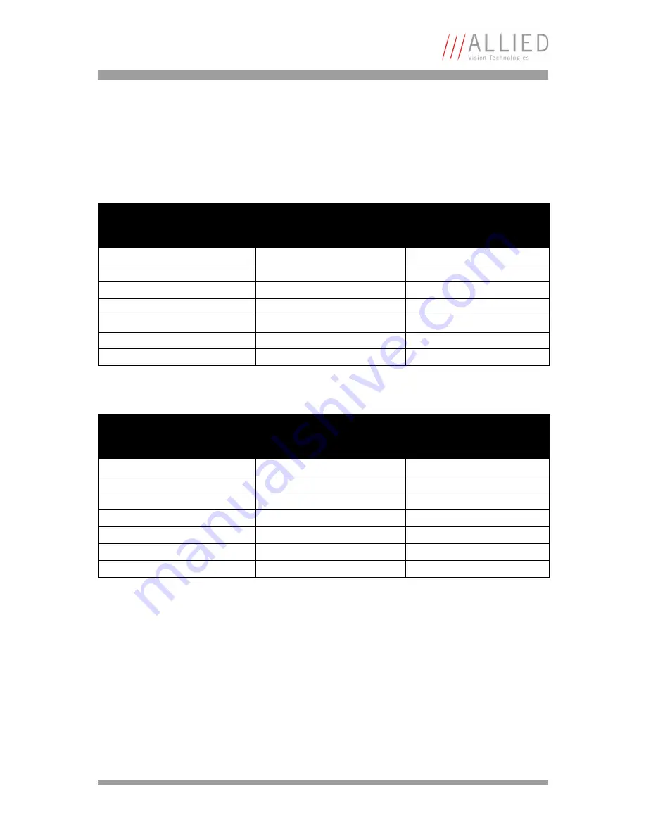
AVT offers different lenses from a variety of manufacturers. The following 
table lists selected image formats depending on camera type, distance and 
the focal width of the lens.

Focal Width
for type 1/2 sensors
Guppy F-046

Distance = 0.5 m

Distance = 1 m

4.8 mm

0.5 m x 0.67 m

1.0 m x 1.33 m 

8 mm

0.3 m x 0.4 m

0.6 m x 0.8 m

12 mm

0.195 m x 0.26 m

0.39 m x 0.58 m

16 mm

0.145 m x 0.19 m

0.29 m x 0.38 m

25 mm

9.1 cm x 12.1 cm

18.2 cm x 24.2 cm

35 mm

6.4 cm x 8.51 cm

12.8 cm x 17.02 cm

50 mm

4.4 cm x 5.85 cm

8.8 cm x 11.7 cm

 Table 6: Focal width vs. field of view (Guppy F-046)

Focal Width
for type 1/3 sensors
Guppy F-025/029/033/036/080

Distance = 0.5 m

Distance = 1 m

4.8 mm

0.375 m x 0.5 m

0.75 m x 1 m 

8 mm

0.22 m x 0.29 m

0.44 m x 0.58 m

12 mm

0.145 m x 0.19 m

0.29 m x 0.38 m

16 mm

11 cm x 14.7 cm

22 cm x 29.4 cm

25 mm

6.9 cm x 9.2 cm

13.8 cm x 18.4 cm

35 mm

4.8 cm x 6.4 cm

9.6 cm x 12.8 cm

50 mm

3.3 cm x 4.4 cm

6.6 cm x 8.8 cm

 Table 7: Focal width vs. field of view (Guppy F-025/029/033/036/080)

Summary of Contents for Guppy

Page 1: ...Technical Manual V4 0 1 02 February 2007 Allied Vision Technologies GmbH Taschenweg 2a D 07646 Stadtroda Germany AVT Guppy ...

Page 2: ...radio noise emissions set out in the Radio Interference Regulations Pour utilisateurs au Canada Cet appareil est conforme aux normes classe B pour bruits radioélectriques spécifiées dans le Règlement sur le brouillage radioélectrique Life support applications These products are not designed for use in life support appliances devices or systems where malfunction of these products can reasonably be ...

Page 3: ...uctions 14 Safety instructions for board level cameras 15 Environmental conditions 17 Guppy types and highlights 18 System components 21 Old CS C Mounting 21 New CS C Mounting 22 Guppy board level cameras 23 IR cut filter 24 Camera lenses 25 Specifications 26 Guppy F 033B 26 Guppy F 033C 28 Guppy F 033B BL board level 30 Guppy F 033C BL board level 32 Guppy F 036B 34 Guppy F 036C 36 Guppy F 046B 3...

Page 4: ... balance 71 One push automatic white balance 74 Automatic white balance 75 Manual gain 77 Auto gain 77 Setting the brightness black level or offset 80 Auto shutter 81 Look up table LUT and gamma function 84 Loading a LUT into the camera 85 Binning b w models 87 2 x and 4 x binning 87 2 x vertical binning and 4 x vertical binning 88 2 x horizontal binning and 4 x horizontal binning 89 2 x full binn...

Page 5: ...set 130 Exposure time of CMOS sensor GUPPY F 036 130 Example GUPPY F 036 130 Camera offsets 130 Example GUPPY F 033 131 Extended shutter 131 One Shot 132 One shot command on the bus to start of exposure 133 End of exposure to first packet on the bus 133 Multi shot 135 ISO_Enable Free Run 135 Asynchronous broadcast 135 Jitter at start of exposure 136 User profiles 137 Video formats modes and bandwi...

Page 6: ...er for video frame rate and base address 165 Inquiry register for basic function 174 Inquiry register for feature presence 175 Inquiry register for feature elements 177 Inquiry register for absolute value CSR offset address 180 Status and control register for feature 181 Feature control error status register 182 Video mode control and status registers for Format_7 182 Quadlet offset Format_7 Mode_...

Page 7: ...y 203 Mirror image only Guppy F 036 204 Pulse width modulation board level cameras only 204 Soft Reset 205 User profiles 206 Error codes 207 Reset of error codes 207 Stored settings 208 GPDATA_BUFFER 209 Firmware update 210 Glossary 211 Index 232 ...

Page 8: ...wing in Figure 18 Camera dimensions new CS C Mounting on page 57 New CAD drawing in Figure 25 Guppy C Mount dimensions new CS C Mounting on page 64 New CAD drawing in Figure 27 Guppy CS Mount dimensions new CS C Mounting on page 66 New CS Mount and C Mount adapter in Chapter Guppy types and highlights on page 18 Added Guppy F 33B C BL board level version Changed camera status register Table 94 Cam...

Page 9: ...er case Register REGISTER Italics Modes fields Mode Parentheses and or blue Links Link Table 2 Styles Note L This symbol highlights important information Caution a This symbol highlights important instructions You have to follow these instructions to avoid malfunctions Caution ESD This symbol highlights important ESD instructions Only qualified personnel is allowed to install and operate compo nen...

Page 10: ... highest demands for quality on our cameras This Technical Manual is the guide to the installation and setting up of the camera for oper ation You will also find the specifications and interfaces here Note L Please read through this manual carefully before operating the camera ...

Page 11: ...N 55022 EN 55024 EN 61000 FCC Class B RoHS 2002 95 EC following the provisions of 89 336 EEC directive s amended by directive 91 263 EEC 92 31 EEC and 93 68 EEC Category name Model name Digital camera IEEE 1394 Guppy F 025B Guppy F 025C Guppy F 029B Guppy F 029C Guppy F 033B Guppy F 033C Guppy F 033B BL board level Guppy F 033C BL board level Guppy F 036B Guppy F 036C Guppy F 046B Guppy F 046C Gup...

Page 12: ...Declarations of conformity GUPPY Technical Manual V4 0 1 12 Note L Customer samples may not comply with above regulations ...

Page 13: ...W Voltage Directive 73 23 EEC as amended by the CE Marking Reference documents applicable in Japan The reference documents include Electronic Equipment Technology Criteria by the Ministry of Trading and Industry Similar to NFPA 70 Note L There are no switches or parts inside the camera that require adjustment The guarantee becomes void upon opening the camera casing If the product is disassembled ...

Page 14: ...onnectors Although IEEE 1394a is functionally plug and play the physical ports may be damaged by excessive ESD elec trostatic discharge when connected under powered conditions It is good practice to bring the metal part which is the shield of the IEEE 1394 cable in contact with the housing of the camera before plugging it into the camera and at the other end in contact with metal parts of the comp...

Page 15: ...ge handle all static sensitive boards and components in a static safe work area Follow the procedures below ESD electrostatic discharge Static electricity can damage the sensor board or the main board of your Board level cameras To prevent static damage dis charge static electricity from your body before you touch any of your Board level cameras s electronic com ponents such as sensor board or mai...

Page 16: ...bles of your board level cameras Keep your board level cameras away from radiators and heat sources Do not spill food or liquids on your board level cameras Caution a Board level cameras Loading Avoid any mechanical forces to the board level cameras the boards and its components especially torsional tensile and compressive forces Any of these forces may result in damage of the board level cameras ...

Page 17: ...al V4 0 1 17 Environmental conditions Housing temperature when camera in use 5 C 50 C Ambient temperature during storage 10 C 60 C Relative humidity 20 80 without condensation Protection for cased models IP 30 Protection for board level IP 00 ...

Page 18: ...family consists of the following models Operating in 8 bit mode CCD b w only the cameras ensure very high quality images under almost all circumstances The GUPPY is equipped with an asyn chronous trigger shutter as well as true partial scan and integrates numerous useful and intelligent smart features for image processing GUPPY type Sensor Picture size Frame rates GUPPY F 025B C Type 1 3 SONY ICX4...

Page 19: ...nted directly in the CS Mount adapter Stan dard delivery is a CS Mount camera Taking out the filter or protection glass is not possible at cus tomer site Ask your dealer for a camera with the respective filter already installed C Mount models have the filter or protection glass mounted in the CS to C Mount extension adapter Ask your dealer for an extension adapter with the intended filter already ...

Page 20: ...ical Manual V4 0 1 20 Warning a Mount dismount lenses and filters in a dust free environ ment and do not use compressed air which can push dust into cameras and lenses Use only optical quality tissue cloth if you must clean a lens or filter ...

Page 21: ...g system components AVT Guppy C Mount camera 4 5 m 1394 standard cable Color version Jenofilt 217 IR cut filter built in B w version only protection glass no filter CD with driver and documentation Optional tripod adapter Optional 4 5 m latching cable Optional HIROSE connector for cable mount HR25 7TP 8S Figure 1 System components ...

Page 22: ...AVT Guppy CS Mount camera 4 5 m 1394 standard cable Color version Jenofilt 217 IR cut filter built in B w version only protection glass no filter 5 mm C Mount adapter CD with driver and documentation Optional tripod adapter Optional 4 5 m latching cable Optional HIROSE connector for cable mount HR25 7TP 8S Figure 2 System components ...

Page 23: ...ur Guppy board level camera To prevent static damage discharge static electricity from your body before you touch any of your Guppy board level camera s electronic components such as sensor board or main board To do so use a static safe workarea with static dissipative mat and wear a static dissipative wrist strap Do not hold any components of your Guppy board level camera against your clothing Ev...

Page 24: ...ate the properties of the camera all examples in this manual are based on the FirePackage OHCI API software and the SmartView application www Ý These utilities can be obtained from Allied Vision Technologies AVT A free version of SmartView is available for download at www alliedvisiontec com Note L The camera also works with all IIDC formerly DCAM compat ible IEEE 1394 programs and image processin...

Page 25: ...m 0 145 m x 0 19 m 0 29 m x 0 38 m 25 mm 9 1 cm x 12 1 cm 18 2 cm x 24 2 cm 35 mm 6 4 cm x 8 51 cm 12 8 cm x 17 02 cm 50 mm 4 4 cm x 5 85 cm 8 8 cm x 11 7 cm Table 6 Focal width vs field of view Guppy F 046 Focal Width for type 1 3 sensors Guppy F 025 029 033 036 080 Distance 0 5 m Distance 1 m 4 8 mm 0 375 m x 0 5 m 0 75 m x 1 m 8 mm 0 22 m x 0 29 m 0 44 m x 0 58 m 12 mm 0 145 m x 0 19 m 0 29 m x...

Page 26: ...C Mount 17 526 mm in air Ø 25 4 mm 32 tpi mechanical flange back to filter distance 9 5 mm see Figure 25 Guppy C Mount dimensions new CS C Mounting on page 64 CS Mount 12 526 mm in air Ø 25 4 mm 32 tpi mechanical flange back distance 8 mm see Figure 27 Guppy CS Mount dimensions new CS C Mounting on page 66 Picture sizes 640 x 480 pixels Format_0 656 x 494 pixels Format_7 Mode_0 Cell size 7 4 µm x ...

Page 27: ...condensation Regulations EN 55022 EN61000 EN55024 FCC Class B DIN ISO 9022 RoHS 2002 95 EC Options old Board level OEM version C Mount IR cut filter IR pass filter available as CS to C Mount adapter CS Mount Consult factory or your dealer for specific filters AVT FirePackage SDK and Viewer 100 control the bus AVT Direct FirePackage SDK and Viewer compatible to DirectX and WDM AVT Fire4Linux SDK an...

Page 28: ...Gain control Manual 0 24 dB 0 0351 dB step auto gain select AOI Shutter speed 20 67 108 864 µs 67s auto shutter select AOI External trigger shutter Trigger_Mode_0 Trigger_Mode_1 advanced feature Trigger_Mode_15 bulk trigger delay Look up table One user programmable 10 bit Æ 8 bit gamma 0 5 Smart functions AGC auto gain control AEC auto exposure control AWB auto white balance LUT look up table one ...

Page 29: ...e4Linux SDK and Viewer compatible to RedHat and Suse Distributions Options new Board level OEM version C CS Mount AR coated protection glass available as CS Mount adapter AVT FirePackage SDK and Viewer 100 control the bus AVT Direct FirePackage SDK and Viewer compatible to DirectX and WDM AVT Fire4Linux SDK and Viewer compatible to RedHat and Suse Distributions Note L The design and specifications...

Page 30: ...Manual 0 24 dB 0 0351 dB step auto gain select AOI Shutter speed 20 67 108 864 µs 67s auto shutter select AOI External trigger shutter Trigger_Mode_0 Trigger_Mode_1 advanced feature Trigger_Mode_15 bulk trigger delay Look up table One user programmable 10 bit Æ 8 bit gamma 0 5 Smart functions AGC auto gain control AEC auto exposure control LUT look up table 4 free configurable inputs outputs with ...

Page 31: ...glass M12 lenses 1394 adapter cable I O adapter cable AVT FirePackage SDK and Viewer 100 control the bus AVT Direct FirePackage SDK and Viewer compatible to DirectX and WDM AVT Fire4Linux SDK and Viewer compatible to RedHat and Suse Distributions Note L The design and specifications for the products described above may change without notice Feature Specification Table 10 Specification Guppy F 033B...

Page 32: ...mat_7 up to 58 fps Gain control Manual 0 24 dB 0 0351 dB step auto gain select AOI Shutter speed 20 67 108 864 µs 67s auto shutter select AOI External trigger shutter Trigger_Mode_0 Trigger_Mode_1 advanced feature Trigger_Mode_15 bulk trigger delay Look up table One user programmable 10 bit Æ 8 bit gamma 0 5 Smart functions AGC auto gain control AEC auto exposure control AWB auto white balance LUT...

Page 33: ... built in IR cut filter protection glass M12 lenses 1394 adapter cable I O adapter cable AVT FirePackage SDK and Viewer 100 control the bus AVT Direct FirePackage SDK and Viewer compatible to DirectX and WDM AVT Fire4Linux SDK and Viewer compatible to RedHat and Suse Distributions Note L The design and specifications for the products described above may change without notice Feature Specification ...

Page 34: ...ng average 188 x 480 pixels Format_7 Mode_4 4 x H binning average 752 x 120 pixels Format_7 Mode_5 4 x V binning average 188 x 120 pixels Format_7 Mode_6 4 x full binning average Cell size 6 0 µm x 6 0 µm ADC 10 bit Data path 8 bit Frame rates 15 fps 30 fps 60 fps variable frame rates in Format_7 from 10 fps up to 64 fps Gain control Manual 0 12 dB average 0 25 dB step for details see Chapter Manu...

Page 35: ...le as CS to C Mount adapter CS Mount Consult factory or your dealer for specific filters AVT FirePackage SDK and Viewer 100 control the bus AVT Direct FirePackage SDK and Viewer compatible to DirectX and WDM AVT Fire4Linux SDK and Viewer compatible to RedHat and Suse Distributions Options new C CS Mount IR cut filter IR pass filter available as CS Mount adapter AVT FirePackage SDK and Viewer 100 c...

Page 36: ...n control Manual 0 12 dB average 0 25 dB step for details see Chapter Manual gain on page 77 Shutter speed 20 µs 979 ms External trigger shutter Trigger_Mode_0 trigger delay Look up table One user programmable 10 bit Æ 8 bit gamma 0 5 Smart functions AWB auto white balance LUT look up table mirror one configurable input three configurable outputs RS 232 port serial port IIDC V1 3 1 Transfer rate 1...

Page 37: ...M AVT Fire4Linux SDK and Viewer compatible to RedHat and Suse Distributions Options new C CS Mount AR coated protection glass available as CS Mount adapter AVT FirePackage SDK and Viewer 100 control the bus AVT Direct FirePackage SDK and Viewer compatible to DirectX and WDM AVT Fire4Linux SDK and Viewer compatible to RedHat and Suse Distributions Feature Specification Table 13 Specification Guppy ...

Page 38: ...ps Gain control Manual 0 24 dB 0 0351 dB step auto gain select AOI Shutter speed 20 67 108 864 µs 67s auto shutter select AOI External trigger shutter Trigger_Mode_0 Trigger_Mode_1 advanced feature Trigger_Mode_15 bulk trigger delay Look up table One user programmable 10 bit Æ 8 bit gamma 0 5 Smart functions AGC auto gain control AEC auto exposure control LUT look up table one configurable input t...

Page 39: ...SDK and Viewer compatible to DirectX and WDM AVT Fire4Linux SDK and Viewer compatible to RedHat and Suse Distributions Options new Board level OEM version C CS Mount IR cut filter IR pass filter available as CS Mount adapter AVT FirePackage SDK and Viewer 100 control the bus AVT Direct FirePackage SDK and Viewer compatible to DirectX and WDM AVT Fire4Linux SDK and Viewer compatible to RedHat and S...

Page 40: ...Gain control Manual 0 24 dB 0 0351 dB step Auto gain select AOI Shutter speed 20 67 108 864 µs 67s Auto shutter select AOI External trigger shutter Trigger_Mode_0 Trigger_Mode_1 Advanced feature Trigger_Mode_15 bulk Trigger delay Look up table One user programmable 10 bit Æ 8 bit gamma 0 5 Smart functions AGC auto gain control AEC auto exposure control AWB auto white balance LUT look up table one ...

Page 41: ...e4Linux SDK and Viewer compatible to RedHat and Suse Distributions Options new Board level OEM version C CS Mount AR coated protection glass available as CS Mount adapter AVT FirePackage SDK and Viewer 100 control the bus AVT Direct FirePackage SDK and Viewer compatible to DirectX and WDM AVT Fire4Linux SDK and Viewer compatible to RedHat and Suse Distributions Note L The design and specifications...

Page 42: ... to 30 fps Gain control Manual 0 24 dB 0 0351 dB step auto gain select AOI Shutter speed 20 67 108 864 µs 67s auto shutter select AOI External trigger shutter Trigger_Mode_0 Trigger_Mode_1 advanced feature Trigger_Mode_15 bulk image transfer by command trigger delay Look up table One user programmable 10 bit Æ 8 bit gamma 0 5 Smart functions AGC auto gain control AEC auto exposure control LUT look...

Page 43: ...Package SDK and Viewer compatible to DirectX and WDM AVT Fire4Linux SDK and Viewer compatible to RedHat and Suse Distributions Options new Board level OEM version C CS Mount IR cut filter IR pass filter available as CS Mount adapter AVT FirePackage SDK and Viewer 100 control the bus AVT Direct FirePackage SDK and Viewer compatible to DirectX and WDM AVT Fire4Linux SDK and Viewer compatible to RedH...

Page 44: ... 30 fps Gain control Manual 0 24 dB 0 0351 dB step Auto gain select AOI Shutter speed 20 67 108 864 µs 67s Auto shutter select AOI External trigger shutter Trigger_Mode_0 Trigger_Mode_1 Advanced feature Trigger_Mode_15 bulk image transfer by command Trigger delay Look up table One user programmable 10 bit Æ 8 bit gamma 0 5 Smart functions AGC auto gain control AEC auto exposure control AWB Auto Wh...

Page 45: ... AVT Fire4Linux SDK and Viewer compatible to RedHat and Suse Distributions Options new Board level OEM version C CS Mount AR coated protection glass available as CS Mount adapter AVT FirePackage SDK and Viewer 100 control the bus AVT Direct FirePackage SDK and Viewer compatible to DirectX and WDM AVT Fire4Linux SDK and Viewer compatible to RedHat and Suse Distributions Note L The design and specif...

Page 46: ...51 dB step auto gain select AOI Shutter speed 20 67 108 864 µs 67s auto shutter select AOI External trigger shutter Trigger_Mode_0 Trigger_Mode_1 advanced feature Trigger_Mode_15 bulk image transfer by command trigger delay Look up table One user programmable 10 bit Æ 8 bit gamma 0 5 Smart functions AGC auto gain control AEC auto exposure control LUT look up table 4 free configurable inputs output...

Page 47: ...tection glass M12 lenses 1394 adapter cable I O adapter cable AVT FirePackage SDK and Viewer 100 control the bus AVT Direct FirePackage SDK and Viewer compatible to DirectX and WDM AVT Fire4Linux SDK and Viewer compatible to RedHat and Suse Distributions Note L The design and specifications for the products described above may change without notice Feature Specification Table 18 Guppy F 080B BL bo...

Page 48: ...frame rates in Format_7 up to 30 fps Gain control Manual 0 24 dB 0 0351 dB step Auto gain select AOI Shutter speed 20 67 108 864 µs 67s Auto shutter select AOI External trigger shutter Trigger_Mode_0 Trigger_Mode_1 Advanced feature Trigger_Mode_15 bulk image transfer by command Trigger delay Look up table One user programmable 10 bit Æ 8 bit gamma 0 5 Smart functions AGC auto gain control AEC auto...

Page 49: ...12 Mount built in IR cut filter protection glass M12 lenses 1394 adapter cable I O adapter cable AVT FirePackage SDK and Viewer 100 control the bus AVT Direct FirePackage SDK and Viewer compatible to DirectX and WDM AVT Fire4Linux SDK and Viewer compatible to RedHat and Suse Distributions Note L The design and specifications for the products described above may change without notice Feature Specif...

Page 50: ...tions GUPPY Technical Manual V4 0 1 50 Spectral sensitivity Figure 5 Spectral sensitivity of Guppy F 025B without cut filter and optics Figure 6 Spectral sensitivity of Guppy F 025C without cut filter and optics ...

Page 51: ...Specifications GUPPY Technical Manual V4 0 1 51 Figure 7 Spectral sensitivity of Guppy F 029B without cut filter and optics Figure 8 Spectral sensitivity of Guppy F 029C without cut filter and optics ...

Page 52: ...Specifications GUPPY Technical Manual V4 0 1 52 Figure 9 Spectral sensitivity of Guppy F 033B without cut filter and optics Figure 10 Spectral sensitivity of Guppy F 033C without cut filter and optics ...

Page 53: ...Specifications GUPPY Technical Manual V4 0 1 53 Figure 11 Spectral sensitivity of Guppy F 036B without cut filter and optics Figure 12 Spectral sensitivity of Guppy F 036C without cut filter and optics ...

Page 54: ...Specifications GUPPY Technical Manual V4 0 1 54 Figure 13 Spectral sensitivity of Guppy F 046B without cut filter and optics Figure 14 Spectral sensitivity of Guppy F 046C without cut filter and optics ...

Page 55: ...Specifications GUPPY Technical Manual V4 0 1 55 Figure 15 Spectral sensitivity of Guppy F 080B without cut filter and optics Figure 16 Spectral sensitivity of Guppy F 080C without cut filter and optics ...

Page 56: ...ensions GUPPY Technical Manual V4 0 1 56 Camera dimensions Guppy standard housing old CS C Mounting Figure 17 Camera dimensions old CS C Mounting Body size 48 2 mm x 30 mm x 30 mm L x W x H Mass 50 g without lens ...

Page 57: ...amera dimensions GUPPY Technical Manual V4 0 1 57 Guppy standard housing new CS C Mounting Figure 18 Camera dimensions new CS C Mounting Body size 48 2 mm x 30 mm x 30 mm L x W x H Mass 50 g without lens ...

Page 58: ...echnical Manual V4 0 1 58 Guppy board level dimensions Figure 19 Guppy board level dimensions Note L Pixel 1 1 on the sensor marks the pixel in the upper left corner in the image incl lens Sensor Pin1 marks the first sensor pin ...

Page 59: ...Camera dimensions GUPPY Technical Manual V4 0 1 59 Guppy board level CS Mount Figure 20 Guppy board level CS Mount ...

Page 60: ...Camera dimensions GUPPY Technical Manual V4 0 1 60 Guppy board level C Mount Figure 21 Guppy board level version C Mount ...

Page 61: ...Camera dimensions GUPPY Technical Manual V4 0 1 61 Guppy board level M12 Mount Figure 22 Guppy board level version M12 Mount ...

Page 62: ...Camera dimensions GUPPY Technical Manual V4 0 1 62 Tripod adapter Figure 23 Tripod dimensions ...

Page 63: ...Camera dimensions GUPPY Technical Manual V4 0 1 63 Cross section C Mount old CS C Mounting Figure 24 Guppy C Mount dimensions old CS C Mounting ...

Page 64: ...Camera dimensions GUPPY Technical Manual V4 0 1 64 Cross section C Mount new CS C Mounting Figure 25 Guppy C Mount dimensions new CS C Mounting ...

Page 65: ...Camera dimensions GUPPY Technical Manual V4 0 1 65 Cross section CS Mount old CS C Mounting Figure 26 Guppy CS Mount dimensions old CS C Mounting ...

Page 66: ...Camera dimensions GUPPY Technical Manual V4 0 1 66 Cross section CS Mount new CS C Mounting Figure 27 Guppy CS Mount dimensions new CS C Mounting ...

Page 67: ...re described in more detail in the following paragraphs Black and white cameras CCD and CMOS Figure 28 Block diagram b w camera CCD Figure 29 Block diagram b w camera CMOS Sensor Test Pattern IEEE 1394 interface 1394a 8 bit Analog Gain CCD Analog Front End AFE Analog Offset 10 Bit LUT Camera control Camera I O connector RS232 Sensor Test Pattern IEEE 1394 interface 1394a 8 bit Analog Offset Analog...

Page 68: ...mera CMOS Camera Control CCD Analog Front End AFE Test Pattern IEEE 1394 Interface 1394a Camera I O Connector RS232 Sensor Analog Gain Analog Offset 10 bit White Balance 10 bit LUT 8 Bit Camera control CMOS Integrated in sensor Test Pattern IEEE 1394 interface 1394a Camera I O connector RS232 Sensor Analog Offset Analog Gain 10 bit 10 bit LUT 8 bit White balance ...

Page 69: ...ICX404AL Type 1 3 6 Yes HAD 5 59 4 68 9 6x7 5 510 492 GUPPY F 025C ICX404AK GUPPY F 029B CCD SONY ICX405AL Type 1 3 6 Yes HAD 5 59 4 68 9 8x6 3 500 582 GUPPY F 029C ICX405AK GUPPY F 033B CCD SONY ICX424AL Type 1 3 6 Yes HAD 5 79 4 89 7 4x7 4 658 494 GUPPY F 033C ICX424AQ GUPPY F 036B CMOS Micron MT9V022 Type 1 3 5 35 Yes 4 51x2 88 6 0x6 0 752x480 GUPPY F 036C GUPPY F 046B CCD SONY ICX415AL Type 1 ...

Page 70: ...the sensor The mirror is centered to the actual FOV center and can be combined with all image manipulation functions like binning This function is especially useful when the camera is looking at objects with the help of a mirror or in certain microscopy applications To configure this feature in an advanced register See Table 106 Mirror con trol register on page 204 Note L When using the mirror fun...

Page 71: ... the FPGA in order to modify the gain of the two channels with lower output by 9 5 dB in 512 steps relative to the channel with highest output The following screenshot is taken from the datasheet of the AFE and illus trates the details The analog color signal coming in pulse amplitude modulation from the sen sor is in the form of the BAYER color pattern sequence It is initially pro cessed in the C...

Page 72: ...e balance may also be changed From the user s point of view the white balance settings are made in register 80Ch of IIDC V1 3 This register is described in more detail on the next page Figure 33 Signal path of MT9V022 Guppy with CMOS sensor x Pixel output reset minus signal Offset correction Voltage Reg0x48 or result of BLC VREF Reg0x2C Gain Selection Reg0x35 or result of AGC ADC Data 9 0 C2 C1 10...

Page 73: ...ontrol O Control with value in the value field 1 Control with value in the absolute value CSR If this bit 1 the value in the value field has to be ignored 2 4 Reserved One_Push 5 Write Set bit high to start Read Status of the feature Bit high WIP Bit low Ready ON_OFF 6 Write ON or OFF this feature ON 1 Read Status of the feature OFF 0 A_M_MODE 7 Set bit high for Auto feature Read for Mode 0 MANUAL...

Page 74: ... equal i e it assumes that the average of the sampled grid pixels is to be monochrome If the image capture is active e g IsoEnable set in register 614h the frames used by the camera for white balance are also output on the 1394 bus Any previously active image capture is restarted after the completion of white balance Automatic white balance can also be enabled by using an external trigger However ...

Page 75: ... 201 AUTOFNC_AOI affects the auto shutter auto gain and auto white balance fea tures and is independent of the Format7 AOI settings If this feature is switched off the work area position and size represent the current active image size The camera automatically adjusts the settings to the permitted values Due to the fact that the active image size might not be divisible by 4 without a remainder the...

Page 76: ...ried out with the help of the graphics overlay see block diagram function of the camera This area is highlighted when the Show work area bit is set high Note If the adjustment fails and the work area size and or position becomes invalid this feature is automatically switched off make sure to read back the ON_OFF flag if this feature doesn t work as expected Figure 36 AUTOFNC_AOI positioning Note T...

Page 77: ...ture When enabled auto gain adjusts the gain within the default gain limits or within the limits set in advanced register F1000370h in order to reach the brightness set in auto exposure register as reference Increasing the auto exposure value aka target grey value increases the aver age brightness in the image and vice versa The applied algorithm uses a proportional plus integral controller PI con...

Page 78: ...s bit 1 the value in the value field has to be ignored 2 4 Reserved One_Push 5 Write Set bit high to start Read Status of the feature Bit high WIP Bit low Ready ON_OFF 6 Write ON or OFF this feature ON 1 Read Status of the feature OFF 0 A_M_MODE 7 Set bit high for Auto feature Read for Mode 0 MANUAL 1 AUTO 8 19 Reserved Value 20 31 Read Write Value this field is ignored when writing the value in A...

Page 79: ...re OFF 0 A_M_MODE 7 Set bit high for Auto feature Read for Mode 0 MANUAL 1 AUTO 8 19 Reserved Value 20 31 Read Write Value this field is ignored when writing the value in Auto or OFF mode if readout capability is not avail able reading this field has no meaning Table 24 Auto_Exposure CSR Note L Values can only be changed within the limits of gain CSR Changes in auto exposure register only have an ...

Page 80: ...127 gray values Increments are in 8 25 LSB The IIDC register brightness at offset 800h is used for this purpose The following table shows the BRIGHTNESS register Register Name Field Bit Description 0xF1000370 AUTOGAIN_CTRL Presence_Inq 0 Indicates presence of this feature read only 1 3 MAXVALUE Max Value 4 15 Max value 16 19 MINVALUE Min value 20 31 Min value Table 25 Advanced register for auto ga...

Page 81: ...delay with minimum overshot Register Name Field Bit Description 0xF0F00800 BRIGHTNESS Presence_Inq 0 Presence of this feature 0 N A 1 Available Abs_Control 1 Absolute value control O Control with value in the value field 1 Control with value in the absolute value CSR If this bit 1 the value in the value field has to be ignored 2 4 Reserved One_Push 5 Write Set bit high to start Read Status of the ...

Page 82: ...l with value in the absolute value CSR If this bit 1 the value in the value field has to be ignored 2 4 Reserved One_Push 5 Write Set bit high to start Read Sta tus of the feature Bit high WIP Bit low Ready ON_OFF 6 Write ON or OFF this feature ON 1 Read Status of the feature OFF 0 A_M_MODE 7 Set bit high for Auto feature Read for Mode 0 MANUAL 1 AUTO 8 19 Reserved Table 27 Shutter CSR Register Na...

Page 83: ... brightness decreases This is done to achieve the best image quality with lowest noise For increasing brightness priority is given to lowering gain first for the same purpose Note L Values can only be changed within the limits of shutter CSR Changes in auto exposure register only have an effect when auto shutter is enabled Auto exposure limits are 50 205 ...

Page 84: ...he incoming digital data these in turn point to the values of functions which are calculated offline e g with a spreadsheet program This function needs to be loaded into the camera s RAM before use One example of using a LUT is the gamma LUT Output Input 0 5 This is used with all CCD models This is known as compensation for the non linear brightness response of many displays e g CRT monitors The l...

Page 85: ...nce required to load data into the camera Note L The input value is the 10 bit value from the digitizer The gamma LUT of the CCD models outputs the most significant 8 bit as shown above As gamma correction for the CCD models is also imple mented via the look up table it is not possible to use a different LUT when gamma correction is enabled With all CCD models the user LUT will be overridden when ...

Page 86: ... 26 31 Use look up table with LutNo number 0xF1000244 LUT_MEM_CTRL Presence_Inq 0 Indicates presence of this feature read only 1 4 Reserved EnableMemWR 5 Enable write access 6 7 Reserved AccessLutNo 8 15 Reserved AddrOffset 16 31 byte 0xF1000248 LUT_INFO Presence_Inq 0 Indicates presence of this feature read only 1 2 Reserved BitsPerValue 3 7 Bits used per table item NumOfLuts 8 15 Maximum number ...

Page 87: ...tensities The value signifies how high the ratio of noise is in regard to the maximum achievable signal intensity The higher this value the better the signal quality The unit of measurement used is generally known as the decibel dB a logarithmic power level 6 dB is the signal level gain when binning two pixels giving a theoretical SNR improvement of about 3 dB However the advantages of increasing ...

Page 88: ...als are averaged Because the signal is averaged the image will not be brighter as without bin ning Use Format_7 Mode_2 to activate 2 x vertical binning Use Format_7 Mode_5 to activate 4 x vertical binning Figure 39 2 x vertical binning and 4 x vertical binning Note L Vertical resolution is reduced but signal to noise ratio SNR is increased by about 3 to 6 dB 2 x or 4 x binning Note L The image app...

Page 89: ...s are averaged Because the signal is averaged the image will not be brighter as without bin ning Use Format_7 Mode_1 to activate 2 x horizontal binning Use Format_7 Mode_4 to activate 4 x horizontal binning Figure 40 2 x horizontal binning and 4 x horizontal binning Note L Horizontal resolution is reduced but signal to noise ratio SNR is increased by about 3 or 6 dB 2 x or 4 x binning Note L The i...

Page 90: ...g 16 pixel signals from 4 adjacent rows and columns are com bined and their signals are averaged Because the signal is averaged the image will not be brighter as without bin ning Use Format_7 Mode_3 to activate 2 x full binning Use Format_7 Mode_6 to activate 4 x full binning Figure 41 Full binning Note L Signal to noise ratio SNR is increased by about 6 or 12 dB 2 x full or 4 x full binning 2 x f...

Page 91: ...le HDR mode 7 19 Reserved MaxKneePoints 20 23 Read only Maximum number of knee points 2 24 27 Reserved KneePoints 28 31 Number of active knee points max 2 0xF1000284 KNEEPOINT_1 KneeVoltage_1 0 7 Regulation of saturation level KneeVoltage_2 8 15 Regulation of saturation level KneeTime_1 16 31 Not implemented but value must be greater 0 0xF1000288 KNEEPOINT_2 KneeVoltage_3 0 7 Regulation of saturat...

Page 92: ...ormation via so called primary color R G B filters placed over the individual pixels in a BAYER mosaic layout Guppy color cameras have no color interpolation so the BAYER demosaicing has to be done outside the camera in the PC raw mode Figure 42 Bayer pattern of Guppy F 036C Pixel 2 9 Column readout direction Row readout direction ...

Page 93: ... RS232 interface Data written to a specific address in the IEEE 1394 address range will be sent through the serial interface Incoming serial interface data is put in the cam era buffer and can be polled from here via simple read commands Control ling registers enable the settings of baud rates and the check of buffer sizes and serial interface errors Base address for the function is F0F02100h Note...

Page 94: ...0 bps Other values reserved Char_Length 8 15 Character length setting WR Set data length 7 or 8 bit RD Get data length 7 7 bits 8 8 bits Other values reserved Parity 16 17 Parity setting WR Set parity RD Get parity setting 0 None 1 Odd 2 Even Stop_Bit 18 19 Stop bits WR Set stop bit RD Get stop bit setting 0 1 1 1 5 2 2 20 23 Reserved Buffer_Size_Inq 24 31 Buffer Size RD only This field indicates ...

Page 95: ...ead only 0 not ready 1 ready 9 Reserved RDRD 10 Receive data buffer ready Read only 0 not ready 1 ready 11 Reserved ORER 12 Receive data buffer overrun error Read current status 0 no error WR 0 to clear status 1 Ignored FER 13 Receive data framing error Read current status 0 no error WR 0 to clear status 1 Ignored PER 14 Receive data parity error Read current status 0 no error WR 0 to clear status...

Page 96: ...from SIO register to transmit FiFo to TBUF_CNT 008h RECEIVE_BUFFER_STAT US_CONTRL RBUF_ST 0 7 SIO receive buffer status RD Number of bytes pending in receive buffer WR Ignored RBUF_CNT 8 15 SIO receive buffer control WR Number of bytes to be read from the receive FiFo RD Number of bytes left for readout from the receive FiFo 16 31 Reserved 00Ch TRANSMIT_BUFFER_ST ATUS_CONTRL TBUF_ST 0 7 SIO output...

Page 97: ...mit buffer in TBUF_CNT if more data are to be transmitted than fit in the buffer 3 Write character to SIO_DATA_REGISTER beginning at char 0 4 To output more characters repeat from step 1 Note L Contact your local dealer if you require further informa tion or additional test programs or software AVT recommends the use of Hyperterminal or other communication programs to test the functionality of thi...

Page 98: ...ntrol input and output lines The IEEE 1394 connector with lock mechanism provides access to the IEEE 1394 bus and thus makes it possible to control the camera and output frames IEEE 1394 port pin assignment The IEEE 1394 plug is designed for industrial use and has the following pin assignment as per specification Figure 43 Rear view of camera Figure 44 IEEE 1394 connector StatusLEDs 8 pin camera I...

Page 99: ...al 1 Cable power 2 Cable GND 3 TPB 4 TPB 5 TPA 6 TPA Table 32 IEEE 1394 pin assignment Note L Cables with latching connectors on one or both sides can be used and are available with various lengths of 4 5 m or up to 17 5 m Ask your local dealer for more details ...

Page 100: ... the following pin assignment see FireWire connector 1 in Figure 20 Guppy board level CS Mount on page 59 Figure 45 Board level camera IEEE 1394 FireWire connector 1 view on pins Signal Pin Pin Signal TPA 6 1 TPA 7 2 GND TPB 8 3 TPB 9 4 Cable power 10 5 Cable shield Table 33 Board level camera IEEE 1394 pin assignment FireWire connector 1 1 2 3 4 5 6 7 8 9 10 X1 chassis connection TPA TPA TPB TPB ...

Page 101: ...am shows the pinning as viewed in pin direction Note L The part number of the appropriate straight I O connector is HIROSE HR25 7TP 8S AVT article number K7600503 AVT also supplies various I O cables of different lengths a selection is listed below I O cable open 8 pin HIROSE female to open end 2 0 m E1000842 I O cable open 8 pin HIROSE female to open end 5 m E1000843 Figure 46 Camera I O connecto...

Page 102: ...ut2 Out TTL Camera Output 2 3 CameraOut3 Out TTL Camera Output 3 4 CameraIn In TTL Camera Input 5 RxD_RS232 In RS232 Terminal Receive Data 6 TxD_RS232 Out RS232 Terminal Transmit Data 7 ExtPower 8 36V Power Supply 8 GND GND Ground Table 34 Camera I O pin assignment Figure 47 Board level camera I O pin assignment view on pins Pin Signal Direction Level Description 1 GND GND Ground Power 2 ExtPower ...

Page 103: ...ND GND Ground RS232 4 TxD_RS232 Out RS232 Terminal Transmit Data 5 RxD_RS232 In RS232 Terminal Receive Data 6 GND GND Ground 4 x I O 7 UserInOut4 In Out TTL User Input Output 4 8 UserInOut3 In Out TTL User Input Output 3 9 UserInOut2 In Out TTL User Input Output 2 10 UserInOut1 In Out TTL User Input Output 1 Figure 48 Status LEDs Pin Signal Direction Level Description Table 35 Board level camera C...

Page 104: ...us data transmission active indicated asynchronously to transmission over the 1394 bus Table 36 LED indication Class S1 Error codes S2 Warning 1 blink DCAM 2 blinks MISC 3 blinks FPGA 4 blinks Stack 5 blinks FPGA Boot error 1 5 blinks Stack setup 1 blink Stack start 2 blinks No FLASH object 1 blink No DCAM object 1 blink Register mapping 3 blinks VMode_ERROR_STATUS 1 blink FORMAT_7_ERROR_1 2 blink...

Page 105: ... An input voltage of 12 V is recommended for most effi cient use of the camera As mentioned above The camera I O connector sup plies power to the camera via a diode This means that there is no power out at pin 7 if the camera is powered via the bus Consult the factory if you need power out put at this pin instead of power in Note L Guppy board level cameras have 4 bidirectional inputs outputs Outp...

Page 106: ...verted The camera must be set to external triggering to trigger image capture by the trigger signal Absolute maximum ratings Recommended operating conditions Description Input voltage 0 5 V 7 0 V 0 V 5 5 V 5 V CMOS Input rise and fall time Schmitt trigger implemented Input clamping voltage 24 V Input pulse width min 1µs Digital input filter Table 38 Input characteristics Warning a Voltages higher ...

Page 107: ...ame Field Bit Description 0xF1000300 IO_INP_CTRL1 Presence_Inq 0 Indicates presence of this fea ture read only TiedToOutput 1 only board level Guppy Tied to output pin x read only 2 6 Reserved Polarity 7 0 Signal not inverted 1 Signal inverted 8 10 Reserved InputMode 11 15 Mode see Table 40 Input routing on page 108 16 30 Reserved PinState 31 RD Current state of pin 0xF1000304 IO_INP_CTRL2 Same as...

Page 108: ...h IIDC V1 31 there is a standard CSR at register F0F00534 834h to control a delay up to FFFh x timebase value The following table explains the Inquiry register and the meaning of the various bits ID Mode Default 0x00 Off 0x01 Reserved 0x02 Trigger input Input 1 0x03 Reserved 0x04 Reserved 0x05 Reserved 0x06 0x0F Reserved 0x10 0x1F Reserved Table 40 Input routing ...

Page 109: ...2 Reserved One_Push_Inq 3 One push auto mode Con trolled automatically by the camera once Readout_Inq 4 Capability of reading out the value of this feature ON_OFF 5 Capability of switching this feature ON and OFF Auto_Inq 6 Auto Mode Controlled auto matically by the camera Manual_Inq 7 Manual Mode Controlled by user Min_Value 8 19 Min value for this feature Max_Value 20 31 Max value for this featu...

Page 110: ...sence_Inq 0 Presence of this feature 0 Not available 1 Available Abs_Control 1 Absolute value control O Control with value in the value field 1 Control with value in the absolute value CSR If this bit 1 the value in the value field has to be ignored 2 5 Reserved ON_OFF 6 Write ON or OFF this fea ture ON 1 Read Status of the feature OFF 0 7 19 Reserved Value 20 31 Value Table 42 Trigger Delay CSR R...

Page 111: ...ting Conditions Output voltage 0 5 5 V Output current Max 20 mA Table 44 Output characteristics Signal Description IntEna Integration Enable signal This signal displays the time in which exposure was made By using a register this output can be delayed up to 1 05 seconds Fval Frame valid signal This feature signals readout from the sensor This signal Fval follows IntEna Busy signal This signal appe...

Page 112: ...Camera interfaces GUPPY Technical Manual V4 0 1 112 Figure 51 Output block diagram Note L The following signals are high active IntEna FVal Busy Follow Input Direct ...

Page 113: ...if the camera is busy by simply polling the BUSY output Register Name Field Bit Description 0xF1000320 IO_OUTP_CTRL1 Presence_Inq 0 Indicates presence of this fea ture read only PWMCapable 1 Only Guppy board level cameras Indicates if an output pin sup ports the PWM feature See Table 49 PWM configura tion registers on page 117 2 6 Reserved Polarity 7 0 Signal not inverted 1 Signal inverted 8 10 Re...

Page 114: ...ate follows PinState bit 0x02 Integration enable Output 1 0x03 Reserved 0x04 Reserved 0x05 Reserved 0x06 FrameValid 0x07 Busy Output 2 0x08 Follow corresponding input Inp1 Æ Out1 0x09 PWM pulse width modulation Only Guppy board level cameras 0x0A 0x1F Reserved Table 47 Output routing Note L The output mode 0x08 is not available for output pins directly tied to an input pin ...

Page 115: ...age 130 Figure 52 Output impulse diagram Note L The signals can be inverted Caution a Firing a new trigger while IntEna is still active can result in image corruption due to double exposure occurring External Trigger Input falling edge Integration_Enable IntEna IntEna delayed Frame_Valid Fval Busy Delay set by register Trigger_Delay offset Delay set by register IntEna_Delay Trigger_Mode_0 ...

Page 116: ... IntEna output signal but does not delay the image capture As mentioned before it is possible to set the outputs by software Doing so the achievable maximum fre quency is strongly dependent on individual software capabilities As a rule of thumb the camera itself will limit the toggle frequency to not more than 700 Hz Guppy board level camera Description Guppy F 033B BL Board level version of Guppy...

Page 117: ...M feature select output mode 0x09 Control the signal state via the PulseWidth and Period fields all times in microseconds µs Register Name Field Bit Description 0xF1000800 IO_OUTP_PWM1 Presence_Inq 0 Indicates presence of this feature read only 1 Reserved 2 3 Reserved MinPeriod 4 19 Minimum PWM period in µs read only 20 27 Reserved 28 31 Reserved 0xF1000804 PulseWidth 0 15 PWM pulse width in µs Pe...

Page 118: ...ters All values have to be written in microseconds µs in the PWM reg isters therefore remember always the factor 10 6 s Example 1 Set PWM with 1kHz at 30 pulse width Note L Note the following conditions PulseWidth Period Period MinPeriod Formula 1 Minimal maximal period and frequency Formula 2 PWM example 1 periodmin 3µs frequencymax 1 periodmin 1 3µs 333 33kHz frequencymin 1 2 16 6 10 s 15 26Hz p...

Page 119: ...a interfaces GUPPY Technical Manual V4 0 1 119 Example 2 Set PWM with 250 Hz at 12 pulse width Formula 3 PWM example 2 RegPeriod 1 frequency 6 10 s 1 250Hz 6 10 s 4000 RegPulseWidth RegPeriod 12 4000 12 480 ...

Page 120: ...n the sync bit sy of the packet header The video data for each pixel are output in 8 bit format Each pixel has a range of 256 shades of gray The digital value 0 is black and 255 is white The following table provides a description of the video data format for the different modes Source IIDC V1 3 1 specification Figure 55 Isochronous data block packet format Source IIDC V1 3 Figure 56 YUV 4 2 2 and ...

Page 121: ...Camera interfaces GUPPY Technical Manual V4 0 1 121 Figure 57 Y8 and Y16 format Source IIDC V1 3 ...

Page 122: ...Camera interfaces GUPPY Technical Manual V4 0 1 122 Figure 58 Data structure Source IIDC V1 3 ...

Page 123: ...happens thus acting in a frame synchronous way Combined with an external trigger it becomes asynchronous in the sense that it occurs whenever the external trigger occurs Individual images are recorded when an external trigger impulse is present This ensures that even fast moving objects can be grabbed with no image lag and with minimal image blur The external trigger comes in as a TTL signal throu...

Page 124: ...ime according to the value set in the shut ter or extended shutter register Trigger_Mode_1 sets the shutter time according to the active low time of the pulse applied or active high time in the case of an inverting input Figure 59 Trigger_mode_0 and 1 Shutter register value Integration Time External Trigger input as applied at input pin External Trigger input as applied at input pin trigger fallin...

Page 125: ...to trigger a multitude of internal image intakes This is especially useful for Grabbing exactly one image based on the first external trigger Filling the camera s internal image buffer with one external trigger with out overriding images Grabbing an unlimited number of images after one external trigger Sur veillance The next diagram shows this mode in detail Figure 60 Trigger_Mode_15 N x image N c...

Page 126: ...e in the value field 1 Control with value in the absolute value CSR If this bit 1 the value in the value field has to be ignored 2 5 Reserved ON_OFF 6 Write ON or OFF this feature ON 1 Read Status of the feature OFF 0 Trigger_Polarity 7 If Polarity_Inq 1 W 0 for low active input 1 for high active input If Polarity_Inq 0 Read only Trigger_Source 8 10 Select trigger source ID from trigger source ID_...

Page 127: ...iry register and the meaning of the various bits Left Middle Right The last line switches camera back to continuous mode Only one image is grabbed precisely with the first external trigger To repeat rewrite line three Toggle One_Shot bit 0 of the One_Shot register 61C so that only one image is grabbed based on the first external trigger To repeat rewrite line three Toggle Multi_Shot bit 1 of the O...

Page 128: ...o_Inq 6 Auto Mode Controlled automat ically by the camera Manual_Inq 7 Manual Mode Controlled by user Min_Value 8 19 Min value for this feature Max_Value 20 31 Max value for this feature Table 52 Trigger_Delay_Inquiry register Name Field Bit Description 0xF0F00834 TRIGGER_DELAY Presence_Inq 0 Presence of this feature 0 N A 1 Available Abs_Control 1 Absolute value control O Control with value in th...

Page 129: ...art of the integration to be delayed by max 221 µs which is max 2 1 s after a trigger edge was detected Register Name Field Bit Description 0xF1000400 TRIGGER_DELAY Presence_Inq 0 Indicates presence of this fea ture read only 1 5 ON_OFF 6 Trigger delay on off 7 10 DelayTime 11 31 Delay time in µs Table 54 Trigger Delay Advanced CSR Note L Switching trigger delay to ON also switches external Trigge...

Page 130: ...set to 20 µs Exposure time of CMOS sensor GUPPY F 036 The CMOS sensor of GUPPY F 036 enables shutter times in integer multiples of the row time 29 89 µs Example GUPPY F 036 Set Shutter register 100 100 x 20 µs 2000 µs 2000 µs 29 89 µs 66 91 Effective shutter 66 x 29 89 µs 1972 74 µs without offset Camera offsets A camera specific offset is also added to this value It is different for the camera mo...

Page 131: ...µs Table 56 Register value and Timebase for GUPPY F 033 Register Name Field Bit Description 0xF100020C EXTD_SHUTTER Presence_Inq 0 Indicates presence of this feature read only 1 5 ExpTime 6 31 Exposure time in µs Table 57 Extended shutter configuration Note L Exposure times entered via the 81Ch register are mir rored in the extended register but not vice versa Longer integration times not only inc...

Page 132: ...is used to arm it The following screenshot shows the sequence of com mands needed to put the camera into this mode It enables the camera to grab exactly one image with an external trigger edge If there is no trigger impulse after the camera has been armed one shot can be cancelled by clearing the bit Figure 62 One shot control SmartView Read Write Address Value Description 7 wr F0F0061C 80000000 D...

Page 133: ...rigger or a release for ExSync if the camera is externally triggered End of exposure to first packet on the bus After the exposure the CCD or CMOS sensor is read out some data is written into a small FiFo buffer before being transmitted to the bus The time from the end of exposure to the start of transport on the bus is 500 µs 62 5 µs This time jitters with the cycle time of the bus 125 µs 3 wr F0...

Page 134: ...mera Offset Description GUPPY F 025 tbd GUPPY F 029 tbd GUPPY F 033 24 28 µs GUPPY F 036 20 30 µs GUPPY F 046 23 90 µs GUPPY F 080 35 64 µs Table 60 Timing after end of exposure 250 s 8 s Guppy F 033 24 28 s Guppy F 036 20 30 µs Guppy F 046 23 90 s Guppy F 080 35 64 s Timebase x Shutter Offset Exposure Time 500 s 62 5 s ...

Page 135: ...r of images based on an external trigger ISO_Enable Free Run Setting the MSB bit 0 in the 614h register ISO_ENA puts the camera into ISO_Enable mode or Continuous_Shot The camera captures an infinite series of images This operation can be quit by deleting the 0 bit Asynchronous broadcast The camera accepts asynchronous broadcasts This involves asynchronous write requests that use node number 63 as...

Page 136: ...it is common to interleave image exposure of a new frame and output that of the previous one It makes continuous image flow possible even with an external trigger The Micron CMOS sensor of the GUPPY F 036 uses a pipelined global shut ter thus imitating the separate light sensitive and storage area of a CCD For the CCDs the uncertainty time delay before the start of exposure depends on the state of...

Page 137: ...n as memory channels from the IIDC specifica tions The feature is described in Chapter User profiles on page 206 Model Camera idle Camera busy Guppy F 025 tbd ns tbd µs Guppy F 029 tbd ns tbd µs Guppy F 033 40 69 ns 32 29 µs Guppy F 036 29 89 µs 29 89 µs Guppy F 046 33 34 ns 31 73 µs Guppy F 080 30 30 ns 40 45 µs Table 61 Jitter at exposure start Note L Jitter at the beginning of an exposure has n...

Page 138: ...ted from the center of the sensor and without binning GUPPY F 025B GUPPY F 025C tbd GUPPY F 029B GUPPY F 029C tbd Note L The maximum frame rates can only be achieved with shutter settings lower than 1 framerate This means that with default shutter time of 40 ms a camera will not achieve frame rates higher than 25 frames s In order to achieve higher frame rates please reduce the shutter time propor...

Page 139: ...o be converted outside of camera Format Mode Resolution 60 fps 30 fps 15 fps 7 5 fps 3 75 fps 1 875 fps 0 0 160 x 120 YUV444 1 320 x 240 YUV422 2 640 x 480 YUV411 3 640 x 480 YUV422 4 640 x 480 RGB8 5 640 x 480 MONO8 x x x x x x x x x x 6 640 x 480 MONO16 7 0 656 x 494 MONO8 656 x 494 Raw8 58 fps 58 fps 1 2 3 Table 62 Video formats Guppy F 033B Guppy F 033C and board level versions ...

Page 140: ...7 0 752 x 480 MONO8 752 x 480 Raw8 64 fps 64 fps 1 376 x 480 MONO8 43 fps 2 x H binning average 2 752 x 240 MONO8 119 fps 2 x V binning average 3 376 x 240 MONO8 81 fps 2 x full binning average 4 188 x 480 MONO8 37 fps 4 x H binning average 5 752 x 120 MONO8 209 fps 4 x V binning average 6 188 x 120 MONO8 122 fps 4 x full binning average Table 63 Video formats Guppy F 036B Guppy F 036C Note The CM...

Page 141: ...ed outside of camera Format Mode Resolution 60 fps 30 fps 15 fps 7 5 fps 3 75 fps 1 875 fps 0 0 160 x 120 YUV444 1 320 x 240 YUV422 2 640 x 480 YUV411 3 640 x 480 YUV422 4 640 x 480 RGB8 5 640 x 480 MONO8 x x x x x x x x x x 6 640 x 480 MONO16 7 0 780 x 582 MONO8 780 x 582 Raw8 49 4 fps 49 4 fps 1 2 3 Table 64 Video formats Guppy F 046B Guppy F 046C ...

Page 142: ... 7 5 fps 3 75 fps 1 875 fps 0 0 160 x 120 YUV444 1 320 x 240 YUV422 2 640 x 480 YUV411 3 640 x 480 YUV422 4 640 x 480 RGB8 5 640 x 480 MONO8 x x x x x x x x 6 640 x 480 MONO16 1 0 800 x 600 YUV422 1 800 x 600 RGB8 2 800 x 600 MONO8 x x x x x x 3 1024 x 768 YUV422 4 1024 x 768 RGB8 5 1024 x 768 MONO8 x x x x x x x x 6 800 x 600 MONO16 7 1024 x 768 MONO16 7 0 1032 x 778 MONO8 1032 x 778 Raw8 30 fps ...

Page 143: ...d out for most other video formats and modes is fixed by the IIDC specification thereby determining the highest possible frame rate in Format_7 mode the user can set the upper left corner and width and height of the section Area of Interest AOI he is interested in to determine the size and thus the highest possible frame rate Setting the AOI is done in the IMAGE_POSITION and IMAGE_SIZE registers N...

Page 144: ...the sensor and transporting it into the FRAME_BUFFER Time for transferring the image over the FireWire bus Length of the exposure time Figure 65 Area of interest AOI Note L The left position width and the upper position height may not exceed the maximum resolution of the sensor The coordinates for width and height must be divisible by 4 The minimum AOI of the Guppy F036 is limited to 92 x 60 pixel...

Page 145: ...t you can see an example of the autofunction AOI Note L Auto gain of CMOS models is directly controlled by the CMOS sensor the target grey level is fixed to 125 Autofunction AOI does not work with auto gain Auto exposure works in conjunction with auto shutter only and therefore works also with autofunction AOI Figure 66 Example of autofunction AOI Show work area is on Note L For more information s...

Page 146: ...5 µs at 400 Mbit s of bandwidth The tables are divided into three formats F_0 up to VGA F_1 up to XGA and F_2 up to UXGA They enable you to calculate the required bandwidth and to ascertain the number of cameras that can be operated independently on a bus and in which mode The frame rates in video modes 0 to 2 are specified and settings are fixed by IIDC V1 3 In video Format_7 frame rates are no l...

Page 147: ...ixel Frame rate fps 494 58 480 59 460 61 440 64 420 65 400 68 380 70 360 74 340 77 320 80 300 84 280 87 260 93 240 98 220 103 200 110 180 117 160 125 140 134 120 146 100 158 64 186 Table 67 Frame rates Guppy F 033 and board level versions Frame rate f AOI height 0 20 40 60 80 100 120 140 160 180 200 0 50 100 150 200 250 300 350 400 450 500 550 AOI height pixel Frame rate fps ...

Page 148: ...F 036 as function of AOI height AOI height pixel Frame rate fps 480 64 5 400 76 0 320 93 0 240 119 5 180 152 0 120 209 0 64 322 0 Table 68 Frame rates Guppy F 036 as function of AOI height Note L The minimum AOI is 92 x 60 AOI width x AOI height The readout time for one row is constant That means the behavior of a CCD sensor is approximated Frame rate f AOI height 0 50 100 150 200 250 300 350 0 50...

Page 149: ...ght AOI height pixel Frame rate fps 582 49 4 580 49 5 560 50 9 540 52 3 520 53 8 500 55 5 480 57 1 460 59 0 440 60 9 420 63 1 400 65 2 380 67 5 360 70 2 340 72 9 Table 69 Frame rates Guppy F 046 Frame rate f AOI height 0 20 40 60 80 100 120 140 160 180 0 50 100 150 200 250 300 350 400 450 500 550 600 650 AOI height pixel Frame rate fps ...

Page 150: ...th GUPPY Technical Manual V4 0 1 150 320 76 0 300 79 1 280 82 8 260 86 6 240 91 0 220 95 5 200 100 9 180 106 4 160 113 1 140 120 0 120 128 5 100 138 5 80 149 5 64 159 8 AOI height pixel Frame rate fps Table 69 Frame rates Guppy F 046 ...

Page 151: ...rame rate fps Guppy F 080 Frame rate fps Guppy F 080 BL 778 30 93 31 13 768 30 66 31 47 760 30 89 31 74 740 31 0 32 44 720 31 9 33 17 700 32 2 33 94 680 33 1 34 74 660 33 5 35 58 Table 70 Frame rates GUPPY F 080 and board level versions Frame rate f AOI height 0 20 40 60 80 100 120 140 0 100 200 300 400 500 600 700 800 900 AOI height pixel Frame rate fps Guppy F 080 Guppy F 080 BL ...

Page 152: ...5 48 48 420 43 5 50 13 400 44 5 51 90 380 45 7 53 80 360 46 8 55 84 340 48 1 58 05 320 49 4 60 43 300 50 8 63 02 280 52 3 65 84 260 53 9 68 93 240 55 5 72 32 220 57 3 76 06 200 59 1 80 21 180 61 2 84 83 160 63 2 90 03 140 65 5 95 90 120 68 0 102 59 100 70 8 110 28 80 73 6 119 22 64 76 2 127 49 AOI height pixel Frame rate fps Guppy F 080 Frame rate fps Guppy F 080 BL Table 70 Frame rates GUPPY F 08...

Page 153: ...lishes the relationship between the required Byte_Per_Packet size and certain variables for the image It is valid only for Format_7 If the value for BYTE_PER_PACKET is greater than 4096 the maximum data payload the sought after frame rate cannot be attained The attainable frame rate can be calculated using this formula Provision BYTE_PER_PACKET is divisible by 4 ByteDepth based on the following va...

Page 154: ...Example max fps calculation FirePackage Direct FirePackage Fire4Linux 1 Start SmartView 2 Click the Edit settings button 3 Click Adv1 tab 4 In combo box Test images choose Image 1 or another test image 1 Start SmartView for WDM 2 In Camera menu click Settings 3 Click Adv1 tab 4 In combo box Test images choose Image 1 or another test image 1 Start cc1394 viewer 2 In Adjustments menu click on Pictur...

Page 155: ...How does bandwidth affect the frame rate GUPPY Technical Manual V4 0 1 155 Figure 70 Gray bar test image Formula 7 Calculating the gray value Gray value x y MOD256 8 bit mode ...

Page 156: ...no8 mode Test image Description Test image 1 Mono8 raw data see screenshot below Table 73 Test image color cameras Note L The color camera outputs Bayer coded raw data in Mono8 instead of a real Y signal as described in IIDC V1 3 The first pixel of the image is always the red pixel from the sen sor Figure 71 Test image 1 without Debayering with Debayering ...

Page 157: ...by IIDC formerly DCAM Digital Camera Specification published by the IEEE 1394 Trade Association IIDC is primarily concerned with setting memory addresses e g CSR Camera_Status_Register and their meaning In principle all addresses in IEEE 1394 networks are 64 bits long The first 10 bits describe the Bus_Id the next 6 bits the Node_Id Of the subsequent 48 bits the first 16 are is always FFFFh leavin...

Page 158: ... MSB Most Significant Bit LSB Least Significant Bit Example This requires for example that to enable ISO_Enabled mode see Chapter ISO_Enable Free Run on page 135 bit 0 in register 614h the value 80000000 h must be written in the corresponding register Far left Bit 0 Bit 1 Bit 2 Bit 30 Bit 31 MSB LSB Table 74 32 bit register ...

Page 159: ...FireCtrl DLL from the FirePackage API How the camera is switched into ISO_Enabled mode is also shown below WriteQuad m_cmdRegBase CCR_FRAME RATE Frame Rate 29 WriteQuad m_cmdRegBase CCR_VMODE mode 29 WriteQuad m_cmdRegBase CCR_VFORMAT format 29 WriteQuad m_cmdRegBase CCR_TRGMODE extTrigger 0x82000000 0 Sleep 100 WriteQuad m_cmdRegBase CCR_ISOENABLE 0x80000000 Figure 72 Configuration of the camera ...

Page 160: ... based on the camera specific base address Note L If you want to use the Direct access program to read or write to a register enter the following value in the Address field F0F00000h Offset Note L The following assignments are only an example Because the key code can describe the roll of a register the order of some registers is not mandatory Bus info block Offset 0 7 8 15 16 23 24 31 400h 04 29 C...

Page 161: ...des the offset for the Node unique ID leaf node as follows 420h 000002 4 428h The entry with key D1 in the root directory 424h in this case provides the offset for the unit directory as follows 424h 000004 4 434h Offset 0 7 8 15 16 23 24 31 428h 00 02 CRC Node unique ID leaf 42Ch 00 0A 47 01 430h Serial number Table 76 Config ROM ...

Page 162: ... address of the camera control register is thus FFFF F0F00000h The offset entered in the table always refers to the base address of F0F00000h Offset 0 7 8 15 16 23 24 31 434h 00 03 CRC Unit directory 438h 12 00 A0 2D 43Ch 13 00 01 02 440h D4 00 00 01 Table 77 Config ROM Offset 0 7 8 15 16 23 24 31 444h 00 0B CRC Unit dependent info 448h 40 3C 00 00 44Ch 81 00 00 0A 450h 82 00 00 0E 454h 38 00 00 0...

Page 163: ...video format Note L If you want to use the Direct access program to read or write to a register enter the following value in the Address field F0F00000h Offset Offset Name Notes 000h INITIALIZE Assert MSB 1 for Init Table 79 Camera initialize register Offset Name Field Bit Description 100h V_FORMAT_INQ Format_0 0 Up to VGA non compressed Format_1 1 SVGA to XGA Format_2 2 SXGA to UXGA Format_3 3 5 ...

Page 164: ... x 600 YUV 4 2 2 Mode _1 1 800 x 600 RGB Mode _2 2 800 x 600 MONO8 x Mode _3 3 1024 x 768 YUV 4 2 2 Mode _4 4 1024 x 768 RGB Mode _5 5 1024 x 768 MONO8 x Mode _6 6 800 x 600 MONO16 Mode _7 7 1024 x 768 MONO16 8 31 Reserved zero 188h V_MODE_INQ Format_2 Mode_0 0 1280 x 960 YUV 4 2 2 Mode _1 1 1280 x 960 RGB Mode _2 2 1280 x 960 MONO8 x Mode _3 3 1600 x 1200 YUV 4 2 2 Mode _4 4 1600 x 1200 RGB Mode ...

Page 165: ...o Note L GUPPY cameras do not deliver color formats Therefore Mono8 corresponds to RAW8 Both formats are supported to allow compatibility with IIDC V1 31 and with other camera models Offset Name Field Bit Description 200h V_RATE_INQ Format_0 Mode_0 FrameRate_0 0 Reserved FrameRate _1 1 Reserved FrameRate _2 2 7 5 fps FrameRate _3 3 15 fps FrameRate _4 4 30 fps FrameRate _5 5 60 fps FrameRate _6 6 ...

Page 166: ...ode_2 FrameRate_0 0 1 875 fps FrameRate _1 1 3 75 fps FrameRate _2 2 7 5 fps FrameRate _3 3 15 fps FrameRate _4 4 30 fps FrameRate _5 5 60 fps FrameRate _6 6 120 fps v1 31 FrameRate _7 7 240 fps v1 31 8 31 Reserved zero 20Ch V_RATE_INQ Format_0 Mode_3 FrameRate_0 0 1 875 fps FrameRate _1 1 3 75 fps FrameRate _2 2 7 5 fps FrameRate _3 3 15 fps FrameRate _4 4 30 fps FrameRate _5 5 60 fps FrameRate _...

Page 167: ...ate _1 1 3 75 fps FrameRate _2 2 7 5 fps FrameRate _3 3 15 fps FrameRate _4 4 30 fps FrameRate _5 5 60 fps FrameRate _6 6 120 fps v1 31 FrameRate _7 7 240 fps v1 31 8 31 Reserved zero 218h V_RATE_INQ Format_0 Mode_6 FrameRate_0 0 1 875 fps FrameRate _1 1 3 75 fps FrameRate _2 2 7 5 fps FrameRate _3 3 15 fps FrameRate _4 4 30 fps FrameRate _5 5 60 fps FrameRate _6 6 120 fps v1 31 FrameRate _7 7 240...

Page 168: ...ode_1 FrameRate_0 0 Reserved FrameRate _1 1 Reserved FrameRate _2 2 7 5 fps FrameRate _3 3 15 fps FrameRate _4 4 30 fps FrameRate _5 5 60 fps FrameRate _6 6 120 fps v1 31 FrameRate _7 7 240 fps v1 31 8 31 Reserved zero 228h V_RATE_INQ Format_1 Mode_2 FrameRate_0 0 Reserved FrameRate _1 1 Reserved FrameRate _2 2 7 5 fps FrameRate _3 3 15 fps FrameRate _4 4 30 fps FrameRate _5 5 60 fps FrameRate _6 ...

Page 169: ...ode_4 FrameRate_0 0 1 875 fps FrameRate _1 1 3 75 fps FrameRate _2 2 7 5 fps FrameRate _3 3 15 fps FrameRate _4 4 30 fps FrameRate _5 5 60 fps FrameRate _6 6 120 fps v1 31 FrameRate _7 7 240 fps v1 31 8 31 Reserved zero 234h V_RATE_INQ Format_1 Mode_5 FrameRate_0 0 1 875 fps FrameRate _1 1 3 75 fps FrameRate _2 2 7 5 fps FrameRate _3 3 15 fps FrameRate _4 4 30 fps FrameRate _5 5 60 fps FrameRate _...

Page 170: ...mat_1 Mode_7 FrameRate_0 0 1 875 fps FrameRate _1 1 3 75 fps FrameRate _2 2 7 5 fps FrameRate _3 3 15 fps FrameRate _4 4 30 fps FrameRate _5 5 60 fps FrameRate _6 6 120 fps v1 31 FrameRate _7 7 Reserved 8 31 Reserved zero 240h V_RATE_INQ Format_2 Mode_0 FrameRate_0 0 1 875 fps FrameRate _1 1 3 75 fps FrameRate _2 2 7 5 fps FrameRate _3 3 15 fps FrameRate _4 4 30 fps FrameRate _5 5 60 fps FrameRate...

Page 171: ... Mode_2 FrameRate_0 0 1 875 fps FrameRate _1 1 3 75 fps FrameRate _2 2 7 5 fps FrameRate _3 3 15 fps FrameRate _4 4 30 fps FrameRate _5 5 60 fps FrameRate _6 6 120 fps v1 31 FrameRate _7 7 Reserved 8 31 Reserved zero 24Ch V_RATE_INQ Format_2 Mode_3 FrameRate_0 0 1 875 fps FrameRate _1 1 3 75 fps FrameRate _2 2 7 5 fps FrameRate _3 3 15 fps FrameRate _4 4 30 fps FrameRate _5 5 60 fps FrameRate _6 6...

Page 172: ...at_2 Mode_5 FrameRate_0 0 1 875 fps FrameRate _1 1 3 75 fps FrameRate _2 2 7 5 fps FrameRate _3 3 15 fps FrameRate _4 4 30 fps FrameRate _5 5 60 fps FrameRate _6 6 Reserved FrameRate _7 7 Reserved 8 31 Reserved zero 258h V_RATE_INQ Format_2 Mode_6 FrameRate_0 0 1 875 fps FrameRate _1 1 3 75 fps FrameRate _2 2 7 5 fps FrameRate _3 3 15 fps FrameRate _4 4 30 fps FrameRate _5 5 60 fps FrameRate _6 6 ...

Page 173: ..._INQ_6_x for other Mode_x of Format_6 Always 0 2E0h V CSR_INQ_7_0 0 31 CSR_quadlet offset for Format_7 Mode_0 2E4h V CSR_INQ_7_1 0 31 CSR_quadlet offset for Format_7 Mode_1 2E8h V CSR_INQ_7_2 0 31 CSR_quadlet offset for Format_7 Mode_2 2ECh V CSR_INQ_7_3 0 31 CSR_quadlet offset for Format_7 Mode_3 2F0h V CSR_INQ_7_4 0 31 CSR_quadlet offset for Format_7 Mode_4 2F4h V CSR_INQ_7_5 0 31 CSR_quadlet of...

Page 174: ..._Control_Error_Status_Inq 2 Inquiry for existence of Feature_Control_Error_Status Opt_Func_CSR_Inq 3 Inquiry for Opt_Func_CSR 4 7 1394b_mode_Capability 8 Inquiry for 1394b_mode_Capability 9 15 Reserved Cam_Power_Cntl 16 Camera process power ON OFF capability 17 18 Reserved One_Shot_Inq 19 One Shot transmission capability Multi_Shot_Inq 20 Multi Shot transmission capability 21 27 Reserved Memory_Ch...

Page 175: ... Focus 10 Focus Control Temperature 11 Temperature Control Trigger 12 Trigger Control Trigger_Delay 13 Trigger delay Control White_Shading 14 White Shading Control Frame_Rate 15 Frame Rate Control 16 31 Reserved 408h FEATURE_LO_INQ Zoom 0 Zoom Control Pan 1 Pan Control Tilt 2 Tilt Control Optical_Filter 3 Optical Filter Control 4 15 Reserved Capture_Size 16 Capture Size for Format_6 Capture_Qualit...

Page 176: ...t should still always be activated first Advanced Feature Set Unique Value is 7ACh and CompanyID is A47h 484h PIO_Control_CSR_Inq PIO_Control_Quadlet_Offset 0 31 Quadlet offset of the PIO_Control CSR s from the base address of initial register space Vendor unique 488h SIO_Control_CSR_Inq SIO_Control_Quadlet_Offset 0 31 Quadlet offset of the SIO_Control CSR s from the base address of initial regist...

Page 177: ...ntrolled auto matically by the camera Manual_Inq 7 Manual Mode Controlled by user Min_Value 8 19 Min value for this feature Max_Value 20 31 Max value for this feature 504h AUTO_EXPOSURE_INQ Same definition as Brightness_inq 508h SHARPNESS_INQ Same definition as Brightness_inq 50Ch WHITE_BAL_INQ Same definition as Brightness_inq 510h HUE_INQ Same definition as Brightness_inq 514h SATURATION_INQ Sam...

Page 178: ...Presence of Trigger_Mode 3 20 30 Reserved Trigger_Mode15_Inq 31 Presence of Trigger_Mode 15 534h TRIGGER_DELAY_INQUIRY Presence_Inq 0 Indicates presence of this feature read only Abs_Control_Inq 1 Capability of control with absolute value 2 Reserved One_Push_Inq 3 One push auto mode Con trolled automatically by the camera once Readout_Inq 4 Capability of reading out the value of this feature ON_OF...

Page 179: ...rate 604h CUR V MODE Bits 0 2 for the current video mode 608h CUR V FORMAT Bits 0 2 for the current video format 60Ch ISO Channel Bits 0 3 for channel 6 7 for ISO speed 610h Camera_Power Always 0 614h ISO_EN Continuous_Shot Bit 0 1 for continuous shot 0 for stop 618h Memory_Save Always 0 61Ch One_Shot Multi_Shot Count Number See text 620h Mem_Save_Ch Always 0 624 Cur_Mem_Ch Always 0 628h Vmode_Err...

Page 180: ... ABS_CSR_HI_INQ_6 Always 0 71Ch ABS_CSR_HI_INQ_7 Always 0 720h ABS_CSR_HI_INQ_8 Always 0 724h ABS_CSR_HI_INQ_9 Always 0 728h ABS_CSR_HI_INQ_10 Always 0 72Ch ABS_CSR_HI_INQ_11 Always 0 730h ABS_CSR_HI_INQ_12 Always 0 734 77Fh Reserved Always 0 780h ABS_CSR_LO_INQ_0 Always 0 784h ABS_CSR_LO_INQ_1 Always 0 788h ABS_CSR_LO_INQ_2 Always 0 78Ch ABS_CSR_LO_INQ_3 Always 0 790h 7BFh Reserved Always 0 7C0h ...

Page 181: ...ays 0 for Mono 810h HUE See above Always 0 for Mono 814h SATURATION See above Always 0 for Mono 818h GAMMA See above 81Ch SHUTTER see Advanced Feature Timebase Chapter Shutter CSR on page 82 820h GAIN See above 824h IRIS Always 0 828h FOCUS Always 0 82Ch TEMPERATURE Always 0 830h TRIGGER MODE Can be effected via advanced feature IO_INP_CTRLx 834h 87C Reserved for other FEATURE_HI Always 0 880h Zoo...

Page 182: ... Format_7 Mode_1 which can be read out at F0F002E4h according to Table 82 Frame rate inquiry register on page 165 gives 003C2400h 4 x 003C2400h F09000h so that the base address for the latter Table 89 Format_7 control and status register on page 182 equals to F0000000h F09000h F0F09000h Format_7 control and status register CSR 8C4h CAPTURE QUALITY Always 0 8C8h 8FCh Reserved for other FEATURE_LO A...

Page 183: ...Flag_1 and ErrorFlag_2 are refreshed on each access to the Format_7 Register Contrary to IIDC V1 3 registers relevant to Format_7 are refreshed on each access The Setting_1 bit is automatically cleared after each access When ErrorFlag_1 or ErrorFlag_2 are set and Format_7 is configured no image capture is started Contrary to IIDC V1 3 COLOR_CODING_ID is set to a default value after an INITIALIZE o...

Page 184: ...MERA_STATUS see Table 94 Camera status register on page 191 0XF1000200 MAX_RESOLUTION see Table 95 Max resolution inquiry register on page 192 0XF1000208 TIMEBASE see Table 96 Timebase configuration register on page 192 0XF100020C EXTD_SHUTTER see Table 98 Extended shutter configuration register on page 194 0XF1000210 TEST_IMAGE see Table 99 Test image configuration register on page 195 0XF1000240...

Page 185: ...HUTTER_HI 0XF1000370 AUTOGAIN_CTRL see Table 103 Advanced register for auto gain control on page 200 0XF1000390 AUTOFNC_AOI see Table 104 Advanced register for autofunction AOI on page 202 0xF1000394 AF_AREA_POSITION 0xF1000398 AF_AREA_SIZE 0XF1000400 TRIGGER_DELAY see Table 105 Trigger Delay Advanced CSR on page 203 0XF1000510 SOFT_RESET see Table 107 Soft reset register on page 205 0XF1000550 US...

Page 186: ...chnical Manual V4 0 1 186 Note L Currently all registers can be written without being activated This makes it easier to operate the camera using Directcontrol AVT reserves the right to require activation in future versions of the software ...

Page 187: ...ion 0xF1000010 VERSION_INFO1 µC type ID 0 15 Always 0 µC version 16 31 Bcd coded version number 0xF1000014 0 31 Reserved 0xF1000018 VERSION_INFO3 Camera type ID 0 15 See Table 92 Camera type ID list on page 187 FPGA version 16 31 Bcd coded version number 0xF100001C 0 31 Reserved 0xF1000020 0 31 Reserved 0xF1000024 0 31 Reserved 0xF1000028 0 31 Reserved 0xF100002C 0 31 Reserved 0xF1000030 OrderIDHi...

Page 188: ... board level 215 Guppy F 025B 216 Guppy F 025C 217 Guppy F 029B 218 Guppy F 029C 219 Guppy F 038B 220 Guppy F 038C 221 Guppy F 038NIR B 222 Guppy F 038NIR C 223 Guppy F 044NIR B 224 Guppy F 044NIR C 225 Guppy F 080B BL board level 226 Guppy F 080C BL board level ID decimal Camera type Table 92 Camera type ID list ...

Page 189: ...med bits in the following table these bits might be set or not Register Name Field Bit Description 0xF1000040 ADV_INQ_1 MaxResolution 0 TimeBase 1 ExtdShutter 2 TestImage 3 FrameInfo 4 5 Reserved VersionInfo 6 7 Reserved Look up tables 8 9 Reserved 10 Reserved HDR control 11 Guppy F 036 only 12 Reserved 13 Reserved TriggerDelay 14 Mirror image 15 Guppy F 036 only Soft Reset 16 17 Reserved 18 Reser...

Page 190: ...ay 16 17 23 Reserved Output 1 PWM 24 only board level Output 2 PWM 25 only board level Output 3 PWM 26 only board level Output 4 PWM 27 only board level 28 31 Reserved 0xF1000048 ADV_INQ_3 Camera Status 0 1 3 Reserved Auto Shutter 4 Auto Gain 5 Auto FNC AOI 6 7 31 Reserved 0xF100004C ADV_INQ_4 0 31 Reserved Register Name Field Bit Description Table 93 Advanced feature inquiry register ...

Page 191: ...s Note L Excessive polling of this register may slow down the operation of the camera Therefore the time between two polls of the status register should not be less than 5 milliseconds If the time between two read accesses is lower than 5 milliseconds the response will be delayed Depending on shutter and isochronous settings the sta tus flags might be set for a very short time and thus will not be...

Page 192: ...onfigured as the time base via the TIMEBASE regis ter IDs 0 9 are in bits 28 to 31 See Table 97 Time base ID on page 193 Refer to the following table for code Default time base is 20 µs This means that the integration time can be changed in 20 µs increments with the shutter control Register Name Field Bit Description 0xF1000200 MAX_RESOLUTION MaxHeight 0 15 Sensor height read only MaxWidth 16 31 S...

Page 193: ... The ExpOffset field might be zero for some cameras this has to be assumed as an unknown exposure time offset according to former software versions Note L Time base can only be changed when the camera is in idle state and becomes active only after setting the shutter value ID Time base in µs 0 1 1 2 2 5 3 10 4 20 Default value 5 50 6 100 7 200 8 500 9 1000 Table 97 Time base ID Note L The ABSOLUTE...

Page 194: ... to the ExpTime field and read back the minimum allowed exposure time The longest exposure time for CCD models is 3FFFFFFh corresponding to 67 11 sec Register Name Field Bit Description 0xF100020C EXTD_SHUTTER Presence_Inq 0 Indicates presence of this fea ture read only 1 5 ExpTime 6 31 Exposure time in µs Table 98 Extended shutter configuration register Note L Exposure times entered via the 81Ch ...

Page 195: ...cates presence of this feature read only 1 7 Reserved Image_Inq_1 8 Presence of test image 1 0 N A 1 Available Image_Inq_2 9 Presence of test image 2 0 N A 1 Available Image_Inq_3 10 Presence of test image 3 0 N A 1 Available Image_Inq_4 11 Presence of test image 4 0 N A 1 Available Image_Inq_5 12 Presence of test image 5 0 N A 1 Available Image_Inq_6 13 Presence of test image 6 0 N A 1 Available ...

Page 196: ...ster Register Name Field Bit Description 0xF1000240 LUT_CTRL Presence_Inq 0 Indicates presence of this feature read only 1 5 Reserved ON_OFF 6 Enable disable this feature 7 25 Reserved LutNo 26 31 Use look up table with LutNo number 0xF1000244 LUT_MEM_CTRL Presence_Inq 0 Indicates presence of this feature read only 1 4 Reserved EnableMemWR 5 Enable write access 6 7 Reserved AccessLutNo 8 15 Reserv...

Page 197: ...ze by the number of bytes per gray value in order to get the number of bits read from the sensor Note L Guppy cameras have the gamma feature implemented via a built in look up table Therefore you can not use gamma and your own look up table at the same time Nevertheless you may combine a gamma look up table into your own look up table Note L When using the LUT feature and the gamma feature pay att...

Page 198: ...e set using this register The on off flag acti vates deactivates integration delay The time can be set in µs in DelayTime Note L See Chapter Input on page 106 See Table 39 Input configuration register on page 107 See Table 40 Input routing on page 108 See Chapter Chapter IO_OUTP_CTRL 1 3 on page 113 Note L Please note that only one edge is delayed If IntEna_Out is used to control an exposure it is...

Page 199: ...nq 0 Indicates presence of this feature read only 1 5 Reserved ON_OFF 6 Enable disable integration enable delay 7 11 Reserved DELAY_TIME 12 31 Delay time in µs Table 101 Delayed integration enable configuration register Register Name Field Bit Description 0xF1000360 AUTOSHUTTER_CTRL Presence_Inq 0 Indicates presence of this feature read only 1 31 Reserved 0xF1000364 AUTOSHUTTER_LO 0 5 Reserved Min...

Page 200: ...boundary and gain regulation is in progress increasing the upper auto shutter boundary has no effect on auto gain shutter regulation as long as auto gain regulation is active Auto gain control The table below illustrates the advanced register for auto gain control MinValue and MaxValue limits the range the auto gain feature is allowed to use for the regulation process Both values are initialized w...

Page 201: ...unction AOI AOI means area of interest Use this feature to select the image area work area on which the following autofunctions work auto shutter auto gain auto white balance As a reference it uses a grid of up to 65534 sample points in 2n steps equally spread over the AOI Note L Autofunction AOI is independent from Format_7 AOI settings If you switch off autofunction AOI work area position and wo...

Page 202: ... see note above 7 Reserved YUNITS 8 19 Y units of work area pos beginning with 0 read only XUNITS 20 31 X units of work area pos beginning with 0 read only 0xF1000394 AF_AREA_POSITION Left 0 15 Work area position left coordinate Top 16 31 Work area position top coordinate 0xF1000398 AF_AREA_SIZE Width 0 15 Width of work area size Height 16 31 Height of work area size Table 104 Advanced register fo...

Page 203: ...221 µs which is max 2 1 s after a trigger edge was detected Register Name Field Bit Description 0xF1000400 TRIGGER_DELAY Presence_Inq 0 Indicates presence of this feature read only 1 5 Reserved ON_OFF 6 Trigger delay on off 7 10 Reserved DelayTime 11 31 Delay time in µs Table 105 Trigger Delay Advanced CSR Note L Trigger delay woks with external trigger modes only ...

Page 204: ...modulation board level cameras only Register Name Field Bit Description 0xF1000410 MIRROR_IMAGE Presence_Inq 0 Indicates presence of this feature read only 1 5 Reserved HorzMirror_ON 6 Horizontal mirror on off 1 on 0 off Default off VertMirror_ON 7 Vertical mirror on off 1 on 0 off Default off 8 15 Reserved HorzMirrorInq 16 Horizontal mirror presence VertMirrorInq 17 Vertical mirror presence 18 31...

Page 205: ...ayed by setting the Delay to a value unequal to 0 the delay is defined in 10 ms steps Register Name Field Bit Description 0xF1000510 SOFT_RESET Presence_Inq 0 Indicates presence of this feature read only 1 5 Reserved Reset 6 Initiate reset 7 19 Reserved Delay 20 31 Delay reset in 10 ms steps Table 107 Soft reset register Note L When SOFT_RESET has been defined the camera will respond to further re...

Page 206: ... case profile 0 is the hard coded factory profile and cannot be overwritten After an initialization command startup or reset of the camera the ProfileID also indicates which profile was loaded on startup reset or initialization Register Name Field Bit Description 0xF1000550 USER_PROFILE Presence_Inq 0 Indicates presence of this feature read only Error 1 An error ocurred 2 7 Reserved SaveProfile 8 ...

Page 207: ...ield To go back to the factory default profile 1 Select ProfileID 0 and toggle the SetDefaultID flag set 2 Read back the register and check the ErrorCode field Error codes Reset of error codes The ErrorCode field is set to zero on the next write access You may also reset the ErrorCode by writing to the USER_PROFILE register with the SaveProfile RestoreProfile and SetDefaultID flag not set by writi...

Page 208: ...AMMA gamma on SHUTTER auto on off GAIN TRIGGER_MODE TRIGGER_POLARITY TRIGGER_DELAY ABS_GAIN IMAGE_POSITION AOI IMAGE_SIZE AOI COLOR_CODING_ID BYTES_PER_PACKET TIMEBASE EXTD_SHUTTER IO_INP_CTRL IO_OUTP_CTRL IO_INTENA_DELAY AUTOSHUTTER_CTRL AUTOSHUTTER_LO AUTOSHUTTER_HI AUTOGAIN_CTRL AUTOFNC_AOI on off TRIGGER_DELAY MIRROR_IMAGE LUT_CTRL LutNo ON_OFF is not saved Table 110 User profile stored settin...

Page 209: ...mming the LUT GPDATA_INFO Buffer size query GPDATA_BUFFER Indicates the actual storage range Register Name Field Bit Description 0xF1000FFC GPDATA_INFO 0 15 Reserved BufferSize 16 31 Size of GPDATA_BUFFER byte 0xF1001000 0xF10017FC GPDATA_BUFFER Table 111 GPData buffer register Note L Read the BufferSize before using GPDATA_BUFFER can be used by only one function at a time ...

Page 210: ... Manual V4 0 1 210 Firmware update Firmware updates can be carried out without opening the camera Note L For further information Read the application note How to update Guppy Pike firmware at AVT website or Contact your local dealer ...

Page 211: ...les of the two color chroma components U then V for each com plete sample area For quality comparison only the ratio between those values is important so 4 4 4 could easily be called 1 1 1 however tradi tionally the value for brightness is always 4 with the rest of the values scaled accordingly YUV4 1 1 means chroma subsampling the horizontal color resolution is quartered This is still acceptable ...

Page 212: ...The result is a much faster frame rate and less data to be processed This is also referred to as partial scan Various autofunctions auto shutter auto gain auto white balance act on the AOI Asynchronous shutter The camera CCD starts to accumulate electrons on receipt of an external trigger pulse Asynchronous transmission mode Asynchronous transmission mode is a mode supported by IEEE 1394 FireWire ...

Page 213: ...c the human eye s greater resolving power with green light These elements are referred to as samples and after interpolation become pixels The raw output of Bayer filter cameras is referred to as a Bayer Pattern image Since each pixel is filtered to record only one of the three colors two thirds of the color data is missing from each A demosaicing algorithm is used to interpolate a set of complete...

Page 214: ...s and images from scanners are usually stored in BMP files CCD charge coupled device CCD readout CCDs are analog devices In order to obtain a digital signal that is appro priate for doing quantitative analysis it is necessary to convert the analog signal to a digital format When light is gathered on a CCD and is ready to be read out a series of serial shifts and parallel shifts occurs First the ro...

Page 215: ...white line on a black background that registers on individual pixels in a CCD will be interpreted as a line containing single pixels of each of the pri mary colors registered Color reproduction Color reproduction is the process to reproduce colors on different devices Two common methods used for reproducing color are additive color mix tures and subtractive color mixtures Correlated double samplin...

Page 216: ...mic range Depth of field Depth of field refers to the in focus region of an imaging system When using a lens especially in close proximity objects at and near a certain distance will be in focus whereas other objects in the field of view that are closer or farther away will appear fuzzy or out of focus The depth of the region that appears in focus is called the depth of field Generally speak ing t...

Page 217: ...e transfer of charge between two objects at different electrical potentials While it takes an electrostatic discharge of about 3 000 volt for a human body to feel a shock many of the more sophisticated electronic components can be damaged by charges as low as 10 volt ESD ESD electrostatic discharge Exposure time Exposure time is the amount of time that the sensor is exposed to the light and thus a...

Page 218: ...tivity pattern noise In addition to the reasons men tioned above light pattern noise can be caused by the imager becoming saturated the non uniform clipping effect of the anti blooming circuit and by non uniform photosensitive pixel areas often caused by debris cov ering portions of some pixels FOV FOV field of view see field of view FPN FPN fixed pattern noise Related with the dark current is its...

Page 219: ...n a digital image has a certain level of brightness ranging from black 0 to white 1 These pixel values serve as the input for your com puter monitor Due to technical limitations CRT monitors output these val ues in a nonlinear way Output Inputgamma When unadjusted most CRT monitors have a gamma of 2 5 which means that pixels with a brightness of 0 5 will be displayed with a brightness of only 0 52...

Page 220: ...tandard and has great value for reducing camera system integration costs and for improving ease of use Global pipelined shutter A global pipelined shutter assures that the integration for all pixels starts and stops at the same moment in time The integration of the next image is possible during the readout of the previously captured image Global shutter All pixels are exposed to the light at the s...

Page 221: ... color Hue A hue refers to the gradation of color within the optical spectrum or vis ible spectrum of light Hue may also refer to a particular color within this spectrum as defined by its dominant wavelength or the central tendency of its combined wavelengths For example a light wave with a central ten dency within 565 590 nm will be yellow In an RGB color space hue can be thought of as an angle ϕ...

Page 222: ... cameras With IEEE 1394 compatible products and systems users can transfer video or still images from a camera or camcorder to a printer PC or television with no image degradation The 1394 Trade Asso ciation includes more than 170 companies and continues to grow Members of the 1394 Trade Association The 1394 Trade Association is comprised of more than 170 member com panies Membership is still in a...

Page 223: ...for digital imaging communications to include I O and RS232 handling and adding additional formats Image processing In the broadest sense image processing includes any form of information processing in which the input is an image Many image processing tech niques derive from the application of signal processing techniques to the domain of images two dimensional signals such as photographs or video...

Page 224: ... camera in very dark locations or at night this filter can be removed to allow infrared radiation to hit the image sensor and thus produce images Isochronous transmission mode Isochronous transmission mode is a mode supported by IEEE 1394 FireWire IEEE 1394 supports a guaranteed data path bandwidth and allows for real time transmission of data to from 1394 devices Isochro nous data transfers opera...

Page 225: ...s a measure of the intensity of light with wavelengths weighted accord ing to the luminosity function a standardized model of human brightness perception In English lux is used in both singular and plural Machine vision Machine vision is the application of cameras and computers to cause some automated action based on images received by the camera s in a manu facturing process Generally the term ma...

Page 226: ...andards created by software and hardware industry leaders including Microsoft Apple Compaq Intel Sun Microsystems National Semiconductor and Texas Instruments to assure that software operating systems drivers applica tions works properly with any compliant hardware Optical Character Recognition Optical Character Recognition OCR refers to the use of machine vision cameras and computers to read and ...

Page 227: ...metimes called the resolution though resolution has a more specific definition Pix els can be expressed as a single number as in a three megapixel digital camera which has a nominal three million pixels or as a pair of numbers as in a 640 by 480 display which has 640 pixels from side to side and 480 from top to bottom as in a VGA display and therefore has a total number of 640 480 307 200 pixels T...

Page 228: ...l cameras Higher readout rates mean that more images can be captured in a given length of time RGB The RGB color model utilizes the additive model in which red green and blue light are combined in various ways to create other colors The very idea for the model itself and the abbreviation RGB come from the three pri mary colors in additive light models Note that the RGB color model itself does not ...

Page 229: ...lity of a signal with regard to its reproduction of intensities The value signifies how high the ratio of noise is in regard to the maximum wanted signal intensity expected The higher this value the better the signal quality The unit of measure ment used is generally known as the decibel dB a logarithmic power level 6 dB is the signal level at approximately a factor of 2 However the advantages of ...

Page 230: ...ensing area Pixel aperture dimension ratio Defines the pixel dimension the ratio of its width to height This parameter describes the resolution granularity and the reproduction behavior of an image sensor area Aspect ratio deviation Shows the ratio between frame store data and true dimensions of an image Sub sampling Sub sampling is the process of skipping neighboring pixels with the same color wh...

Page 231: ... g by differing illumination conditions YUV The YUV model defines a color space in terms of one luminance and two chrominance components YUV is used in the PAL and NTSC systems of tele vision broadcasting which are the standards in much of the world YUV models human perception of color more closely than the standard RGB model used in computer graphics hardware but not as closely as the HSL color s...

Page 232: ...alance 75 AUTOSHUTTER_CTRL 82 AUTOSHUTTER_HI 82 AUTOSHUTTER_LO 82 AUTO_EXPOSURE 79 Auto_Exposure CSR 79 Auto_Inq 109 A_M_MODE Field 73 78 79 81 82 B bandwidth 138 affect frame rate 153 frame rates 146 BAYER mosaic 92 binning 87 full 90 horizontal 89 vertical 88 BitsPerValue 86 196 black level 80 black value 77 80 black white camera CCD block diagram 67 black white camera CMOS block diagram 67 blin...

Page 233: ... 153 DCAM 24 138 157 declaration of conformity 11 diagonal 69 Digital Camera Specification 157 digitization 71 digitizer 85 document history 8 double exposure 115 E effective pixels 69 EN 55022 11 EN 55024 11 EN 61000 11 EnableMemWR Field 86 196 End of exposure 133 Environmental conditions 17 environmental conditions 17 error codes LED 104 error states 104 Exposure time Field 131 exposure time 130...

Page 234: ...77 ranges 77 white balance 71 gain CSR 79 80 GAIN Name 78 GAIN register 74 gamma function 84 CMOS models 85 gamma LUT 84 global shutter 123 GPDATA_BUFFER 85 GUPPY Camera types 18 GUPPY F 025B C 18 GUPPY F 029B C 18 Guppy F 033B BL Specification 30 Guppy F 033B Specification 26 GUPPY F 033B C 18 Guppy F 033C BL Specification 32 Guppy F 033C Specification 28 Guppy F 036B Specification 34 GUPPY F 036...

Page 235: ...al 111 198 internal trigger 125 IO_INP_CTRL1 107 IO_INP_CTRL2 107 IO_INP_CTRL3 107 IO_INP_CTRL4 107 IO_OUTP_CTRL1 113 IO_OUTP_CTRL2 113 IO_OUTP_CTRL3 113 IO_OUTP_CTRL4 113 IR cut filter 21 22 Isochronous data block packet format 120 IsoEnable white balance 74 ISO_Enable 135 ISO_Enable mode 135 Iso_Enable mode multi shot 135 one shot 132 I O connector plug 98 I O pinning 102 J Jenofilt 217 IR cut f...

Page 236: ...I API FirePackage 24 One Shot 132 one shot Trigger_Mode_15 125 127 values 133 one shot bit 132 one shot mode 132 One_Push Field 73 78 79 81 82 One_Push_Inq 109 ON_OFF 109 ON_OFF Field 73 operating camera 105 output block diagram 112 signals 111 Output configuration register 113 output lines 98 Output mode 113 output mode 113 114 Output mode Field 113 output pin control 114 outputs 101 111 general ...

Page 237: ... 24 Jenofilt 217 24 Stack setup 104 Stack start 104 standard cable 21 22 standard housing 56 57 status LED 103 styles 9 SVGA 18 symbols 9 system components 21 T Target grey level auto exposure 79 199 test image 154 b w cameras 154 color cameras 156 configuration register 195 gray bar 155 save 195 TEST_IMAGE 195 time base setting 194 time response 133 TIMEBASE 184 192 timebase exposure time 130 MF ...

Page 238: ..._Value Field 73 U V slider range 73 V Vendor unique Features 174 Vertical binning 88 vertical mirror Guppy F 036 70 VGA 18 video data format IIDC 1 3 120 video format available bandwidth 146 frame rate 146 video formats 138 GUPPY F 033 139 140 141 142 video Format_7 AOI 143 video mode CUR V MODE 179 Format_7 182 inquiry register 164 sample C code 159 video mode 0 146 video mode 2 146 VMode_ERROR_S...

Reviews: