background image

Chapter 7: Virtual LANs

78

Section I: Using the Menus Interface

ˆ

Each VLAN has one port connected to the router. The router 
interconnects the various VLANs and functions as a gateway to the 
WAN.

Port-based

Example 2

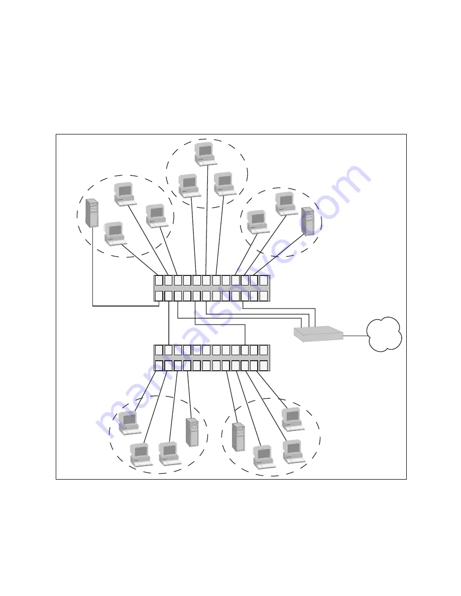
Figure 18 illustrates more port-based VLANs. In this example, Sales and 
Engineering VLANs span two AT-GS950/24 Gigabit Ethernet switches, 
while Production VLAN is limited to just one switch. 

Figure 18. Port-based VLAN - Example 2

WAN

2

3

4

5

6

7

9

19

1

21 23

17

15

11 13

8 10 12 14

18 20 22 24

16

2

3

4

5

6

7

9

19

1

21 23

17

15

11 13

8 10 12 14

18 20 22 24

16

Router

Sales VLAN
(VID 2)

Engineering VLAN
(VID 3)

Production VLAN

(VID 4)

Engineering VLAN

(VID 3)

Sales VLAN

(VID 2)

AT-GS950/24 Gigabit Ethernet Switch

AT-GS950/24 Gigabit Ethernet Switch

Summary of Contents for AT-S79

Page 1: ...613 000207 Rev A Management Software AT S79 User s Guide For use with the AT GS950 16 and AT GS950 24 Smart Switches Version 1 0 0 ...

Page 2: ...arks or registered trademarks of their respective owners Allied Telesyn Inc reserves the right to make changes in specifications and other information contained in this document without prior written notice The information provided herein is subject to change without notice In no event shall Allied Telesyn Inc be liable for any incidental special indirect or consequential damages whatsoever includ...

Page 3: ...nus Interface 26 Quitting from a Local Management Session 27 Chapter 3 Basic Switch Parameters 29 Configuring the IP Address Subnet Mask and Gateway Address 30 Enabling and Disabling the DHCP Client 33 Configuring System Administration Information 34 Setting the User Interface Configuration 36 Viewing Switch Information 39 Rebooting the Switch 42 Pinging a Remote System 44 Returning the AT S79 Man...

Page 4: ...agged Ports 87 Displaying the VLANs 89 Modifying a VLAN 91 Deleting a VLAN 93 Chapter 8 Quality of Service QoS 95 QoS Overview 96 Mapping CoS Priorities to Egress Queues 99 Configuring CoS 102 Chapter 9 802 1x Port based Network Access Control 107 802 1x Port based Network Access Control Overview 108 Authentication Process 109 Authenticator Ports 109 General Steps 111 Port based Network Access Con...

Page 5: ...d Configuring Ports Using the Configuration of Port Page 161 Displaying Port Statistics 164 Chapter 16 Port Trunking 167 Creating a Port Trunk 168 Modifying a Port Trunk 170 Enabling and Disabling a Port Trunk 171 Chapter 17 Port Mirroring 173 Configuring Port Mirroring 174 Disabling Port Mirroring 175 Chapter 18 Virtual LANs 177 Creating a VLAN 178 Configuring the PVID of Untagged Ports 180 Displ...

Page 6: ...Contents 6 ...

Page 7: ...ion Menu 100 Figure 25 Port Priority Configuration Menu 103 Figure 26 Example of the Authenticator Role 110 Figure 27 Port based Authentication Across Multiple Switches 113 Figure 28 Port Based Access Control Configuration Menu 114 Figure 29 RADIUS Server Configuration Menu 121 Figure 30 Storm Control Configuration Menu 127 Figure 31 Software Upgrade Menu 1 of 2 131 Figure 32 Software Upgrade Menu...

Page 8: ...ify VLAN Page 184 Figure 53 QoS Configuration Page 188 Figure 54 Port Priority Configuration Page 190 Figure 55 802 1x Configuration Page 194 Figure 56 RADIUS Configuration Menu 198 Figure 57 Broadcast Storm Control Page 200 Figure 58 IP Configuration Page 203 ...

Page 9: ...9 Table 1 Menus Interface Operations 26 Table 2 Default Mappings of IEEE 802 1p Priority Levels to Egress Port Priority Queues 97 Table 3 AT S79 Default Settings 205 Tables ...

Page 10: ...Tables 10 ...

Page 11: ...ort on the switch The web browser interface can be accessed from any management workstation on your network that has a web browser application For background information on the management interfaces refer to Chapter 1 Overview on page 15 Note The AT S79 management software does not support remote management with the Telnet application protocol or an SNMP program This preface contains the following...

Page 12: ...es The installation and user guides for all Allied Telesyn products are available in portable document format PDF on our web site at www alliedtelesyn com You can view the documents online or download them onto a local workstation or server ...

Page 13: ... following conventions Note Notes provide additional information Caution Cautions inform you that performing or omitting a specific action may result in equipment damage or loss of data Warning Warnings inform you that performing or omitting a specific action may result in bodily injury ...

Page 14: ...to Allied Telesyn without an RMA number will be returned to the sender at the sender s expense To obtain an RMA number contact Allied Telesyn Technical Support through our web site www alliedtelesyn com Sales or Corporate Information You can contact Allied Telesyn for sales or corporate information through our web site www alliedtelesyn com To find the contact information for your country select C...

Page 15: ...fferent methods for accessing the software and the management access levels This chapter contains the following sections Management Overview on page 16 Local Management Connection on page 17 Remote Management Connection on page 18 Management Access Level on page 19 Ports 15 and 16 on the AT GS950 16 Switch and Ports 23 and 24 on the AT GS950 24 Switch on page 20 ...

Page 16: ...u can use the device as an unmanaged switch by connecting it to your network as explained in the hardware installation guide and powering on the unit Note The default settings for the management software are listed in Appendix A AT S79 Software Default Settings on page 205 To actively manage the switch and adjust its operating parameters you must access the switch s AT S79 management software Ther...

Page 17: ...ith the unit This type of connection is referred to as local because you must be physically close to the switch such as in the wiring closet where the switch is located Note For instructions on how to start a local management session refer to Starting a Local Management Session on page 24 A switch does not need an Internet Protocol IP address for you to manage it locally You can start a local mana...

Page 18: ...lly obtains its IP configuration from a DHCP server on the network The initial assignment of an IP address on a switch must be made through a local connection to the unit For instructions on how to start a remote management session refer to Establishing a Remote Connection to Use the Web Browser Interface on page 136 Note In order to remotely manage a switch using a web browser the remote manageme...

Page 19: ... one level of management access manager When you log in as a manager you can view and configure all of a switch s operating parameters You log in as a manager by entering the appropriate username and password when you start an AT S79 management session The default username and password are both manager ...

Page 20: ...ese ports The twisted pair ports are by default the active ports An optional SFP port becomes active when it establishes a link with an end node at which point the corresponding twisted pair port changes to the redundant state A twisted pair port and its corresponding optional SFP port share the same configuration settings including port settings and VLAN assignments When an SFP port establishes a...

Page 21: ...rface on page 23 Chapter 3 Basic Switch Parameters on page 29 Chapter 4 Port Configuration on page 49 Chapter 5 Port Trunking on page 57 Chapter 6 Port Mirroring on page 65 Chapter 7 Virtual LANs on page 71 Chapter 8 Quality of Service QoS on page 95 Chapter 9 802 1x Port based Network Access Control on page 107 Chapter 10 RADIUS Authentication Protocol on page 119 Chapter 11 Broadcast Storm Contr...

Page 22: ...22 Section I Using the Menus Interface ...

Page 23: ...ormation and instructions on how to access the menus interface of the AT S79 management software by starting a local management session This chapter contains the following sections Starting a Local Management Session on page 24 Using the Menus Interface on page 26 Quitting from a Local Management Session on page 27 ...

Page 24: ...ession To start a local management session perform the following procedure 1 Connect one end of the management cable included with the switch to the console port on the switch as shown in Figure 1 Figure 1 Connecting the Management Cable to the Console Port 2 Connect the other end of the cable to the RS 232 port on a terminal or PC with a terminal emulator program 3 Configure the terminal or termi...

Page 25: ... manager Note To change the login name or password refer to Setting the User Interface Configuration on page 36 The Main Menu is shown in Figure 3 Figure 3 Main Menu AT GS950 16 Local Management System Enter the character in square brackets to select option Login Menu Login AT GS950 16 Local Management System Enter the character in square brackets to select option Main Menu G eneral Information B ...

Page 26: ...n enter a value the symbol is displayed For example Enter new password The symbol indicates that you can enter a new value for the parameter or change the existing value After you have entered a value press Enter Changes are immediately activated on the AT GS950 Series switch Table 1 Menus Interface Operations When directed to You must Enter your selection Type the menu option letter Enter informa...

Page 27: ...the switch s configuration if you leave your workstation unattended Note A local management session automatically times out if there is no management activity during a pre defined length of time referred to as the timeout period The timeout feature is intended to protect the parameter settings on the switch from unauthorized changes should you leave your management station unattended during a mana...

Page 28: ...Chapter 2 Getting Started with the Menus Interface 28 Section I Using the Menus Interface ...

Page 29: ...ay Address on page 30 Enabling and Disabling the DHCP Client on page 33 Configuring System Administration Information on page 34 Setting the User Interface Configuration on page 36 Viewing Switch Information on page 39 Rebooting the Switch on page 42 Pinging a Remote System on page 44 Returning the AT S79 Management Software to the Factory Default Values on page 47 ...

Page 30: ...tely manage the device from a remote management station that is separated from the switch by a router To configure the switch to automatically obtain its IP configuration from a DHCP server on your network go to Enabling and Disabling the DHCP Client on page 33 To set the switch s IP configuration perform the following procedure 1 From the Main Menu type B to select Basic Switch Configuration The ...

Page 31: ...ble DHCP Mode option is described in Enabling and Disabling the DHCP Client on page 33 3 To set the switch s IP address do the following a Type I to select Set IP Address The following prompt is displayed Enter new IP address b Type the IP address for the switch and press Enter 4 To set the switch s subnet mask do the following a Type M to select Set Subnet Mask The following prompt is displayed E...

Page 32: ... switch and press Enter 5 To set the switch s gateway address do the following a Type G to select Set Default Gateway The following prompt is displayed Enter new gateway IP address b Type the gateway IP address for the switch and press Enter 6 Type Q to select Quit to previous menu and save your changes ...

Page 33: ...gement station that is separated from the switch by a router The DHCP client is disabled by default on the switch The DHCP client does not support BOOTP servers To activate or deactivate the DHCP client on the switch perform the following procedure 1 From the Main Menu type B to select Basic Switch Configuration The Basic Switch Configuration Menu is shown in Figure 4 on page 30 2 From the Basic S...

Page 34: ...From the Basic Switch Configuration Menu type A to select System Administration Information The System Administration Configuration Menu is shown in Figure 6 Figure 6 System Administration Configuration Menu The Description parameter in the top portion of the menu displays the model name of the switch This parameter cannot be changed 3 To set the system s name do the following a Type N to select S...

Page 35: ...ation do the following a Type L to select Set System Location The following prompt is displayed Enter system location b Type information to describe the location of the switch for instance Third Floor The location is optional and can contain up to 50 characters 5 To enter the administrator s name do the following a Type C to select Set System Contact Information The following prompt is displayed E...

Page 36: ... From the Main Menu type B to select Basic Switch Configuration The Basic Switch Configuration Menu is shown in Figure 4 on page 30 2 From the Basic Switch Configuration Menu type U to select User Interface Configuration The User Interface Configuration Menu is shown in Figure 7 Figure 7 User Interface Configuration Menu The RADIUS Server Configuration option is described Chapter 10 RADIUS Authent...

Page 37: ... but not to a remote web management session A web browser management session remains active so long as your web browser is open Note If you select 0 you must always remember to properly log off from a local management session when you are finished to prevent blocking future management sessions with the switch 4 To enable or disable the web server do the following a Type W to select Enable Disable ...

Page 38: ... Type P to select Change Administrator Password The following prompt is displayed Enter old password b Enter the current manager password and press Enter The following prompt is displayed Enter new password c Type the new password and press Enter The password can be from 0 to 12 characters Allied Telesyn recommends not using special characters such as spaces and exclamation points The password is ...

Page 39: ...last reset or power cycle Runtime Image The version of the runtime software Boot Loader The version of the boot loader software AT GS950 16 Local Management System Main Menu General Information System up for 24min s 36sec s Runtime Image Version 1 0 Boot Loader Version 1 0 Hardware Information Version DRAM Size 16MB Fixed Baud Rate 9600bps Flash Size 4 MB Administration Information Switch Name Mar...

Page 40: ...tact refer to Configuring System Administration Information on page 34 System Address Information Section MAC Address The MAC address of the switch You cannot change this information System IP Address The IP address of the switch Refer to Configuring the IP Address Subnet Mask and Gateway Address on page 30 to manually assign an IP address or Enabling and Disabling the DHCP Client on page 33 to ac...

Page 41: ...e Menus Interface 41 Automatic Network Features Section DHCP Mode The status of the DHCP client on the switch For information about setting this parameter refer to Enabling and Disabling the DHCP Client on page 33 2 Press any key to return to the previous menu ...

Page 42: ...tion The switch does not forward network traffic during the reboot process Some network traffic may be lost To reboot the switch perform the following procedure 1 From the Main Menu type T to select Switch Tools The Switch Tools Configuration Menu is shown in Figure 9 Figure 9 Switch Tools Configuration Menu 2 From the Switch Tools Configuration Menu type R to select System Reboot AT GS950 16 Loca...

Page 43: ...ype R to select Start Reboot Process The following prompt is displayed Are you sure you want to reboot the system Y N 6 Type Y to start the reboot process or N to cancel the reboot The switch immediately begins to reload the AT S79 management software This process takes approximately one minute to complete You can not manage the device during the reboot After the reboot is finished you can log in ...

Page 44: ...hrough which the node is communicating with the switch must be an untagged or tagged member of the Default VLAN To ping a network device perform the following procedure 1 From the Main Menu type T to select Switch Tools The Switch Tools Configuration Menu is shown in Figure 9 on page 42 2 From the Switch Tools Configuration Menu type P to select Ping Execution The Ping Execution Menu is shown in F...

Page 45: ...ts 6 Enter the number of ping requests you want the switch to perform The range is 1 to 10 The default is 10 7 Type T to select Set Timeout Value The following prompt is displayed Enter new timeout value 8 Enter the length of time in seconds the switch is to wait for a response before assuming that a ping has failed The range is 1 to 5 seconds The default is 3 seconds 9 Type E to select Execute Pi...

Page 46: ...ct Stop Ping 12 Type Q to select Quit to previous menu AT GS950 16 Local Management System Switch Tools Configuration Ping Execution Target IP Address 149 35 8 33 Number of Requests 4 Timeout Value sec 3 Result No 1 20 ms No 2 20 ms No 3 20 ms No 4 20 ms COMMAND Set Target I P Address E xecute Ping Set N umber of Requests S top Ping Set T imeout Value Q uit to previous menu Command ...

Page 47: ... the following procedure 1 From the Main Menu type T to select Switch Tools The Switch Tools Configuration Menu is shown in Figure 9 on page 42 2 From the Switch Tools Menu type R to select System Reboot to start the reboot The System Reboot menu is shown in Figure 10 on page 43 3 Type O to select Set Reboot Option The following prompt is displayed Select reboot option F I N 4 Type F or I to selec...

Page 48: ...eboot the system Y N 6 Type Y to start the reboot process The switch returns its operating parameters to the default values and begins to reload the AT S79 management software This process takes approximately one minute to complete You can not manage the device during the reboot After the reboot is finished you can log in again if you want to continue to manage the device ...

Page 49: ...res for viewing and adjusting the parameter settings for the ports on the switch This chapter contains the following sections Displaying the Port Parameters on page 50 Enabling and Disabling a Port on page 53 Setting a Port s Speed and Duplex Mode on page 54 Changing the Flow Control Setting on page 56 ...

Page 50: ...enu AT GS950 16 Local Management System Basic Switch Configuration Port Configuration Menu Port Trunk Type Link Status Mode Flow Ctrl 1 1000tx Up Enabled Auto 100F Enabled 2 1000tx Up Enabled Auto 100F Enabled 3 1000tx Up Enabled 100 FDx Enabled 4 1000tx Up Enabled Auto 1000F Enabled 5 1000tx Up Enabled Auto 100F Enabled 6 1000tx Down Enabled Auto Enabled 7 1000tx Up Enabled Auto 1000F Enabled 8 1...

Page 51: ...an end node Status The current operating status of the port The possible values are Enabled The port is able to send and receive Ethernet frames This is the default setting for all ports on the switch Disabled The port has been manually disabled To change a port s status see Enabling and Disabling a Port on page 53 Mode The port s speed and duplex mode setting The possible values are Auto The port...

Page 52: ...o change a port s speed and duplex mode setting see Setting a Port s Speed and Duplex Mode on page 54 Flow Ctrl Whether flow control is enabled on the port Flow control is enabled by default To disable flow control refer to Changing the Flow Control Setting on page 56 3 Type Q to select Quit to previous menu ...

Page 53: ...o select Basic Configuration The Basic Switch Configuration Menu is shown in Figure 4 on page 30 2 From the Basic Switch Configuration Menu type P to select Port Configuration The Port Configuration Menu is shown in Figure 13 on page 50 3 Type S to select Set Status The following prompt is displayed Set Status Enter port number 4 Enter the number of the port you want to enable or disable You can c...

Page 54: ...following prompt is displayed Enter new mode for port n a h H F f t T 5 Enter the letter that corresponds to the desired speed and duplex mode setting for the port The port settings are a Auto The port uses Auto Negotiation to set its speed and duplex mode This is the default setting for all ports h 10 Mbps half duplex f 10 Mbps full duplex H 100 Mbps half duplex F 100 Mbps full duplex t 1000 Mbps...

Page 55: ... on the port and set the port s speed and duplex mode manually Allied Telesyn does not recommend manually setting a 10 100 1000Base T twisted pair port to either 1000 Mbps full duplex or 1000 Mbps half duplex For 1000 Mbps operation Allied Telesyn recommends setting a port to Auto Negotiation The only valid setting for an optional SFP port is Auto Negotiation 6 Type Q to select Quit to previous me...

Page 56: ...end node To change the flow control setting on a port perform the following procedure 1 From the Main Menu type B to select Basic Configuration The Basic Switch Configuration Menu is shown in Figure 4 on page 30 2 From the Basic Switch Configuration Menu type P to select Port Configuration The Port Configuration Menu is shown in Figure 13 on page 50 3 Type S to select Set Status The following prom...

Page 57: ...ng This chapter provides information and procedures for creating a port trunk and contains the following sections Port Trunking Overview on page 58 Creating a Port Trunk on page 59 Modifying a Port Trunk on page 62 Enabling and Disabling a Port Trunk on page 63 ...

Page 58: ...eed duplex mode and flow control settings must be the same on all the ports in a trunk The ports of a trunk must be members of the same VLAN A port trunk cannot consist of ports from different VLANs The ports of a trunk do not have to be consecutive When you cable a trunk the order of the connection should be maintained on both nodes The lowest numbered port in a trunk on the switch should be conn...

Page 59: ... storms and poor network performance To create a port trunk perform the following procedure 1 From the Main Menu type A to select Advanced Switch Configuration The Advanced Switch Configuration Menu is shown in Figure 14 Figure 14 Advanced Switch Configuration Menu 2 From the Advanced Switch Configuration Menu type T to select Trunk Configuration AT GS950 24 Local Management System Main Menu Advan...

Page 60: ...ude in the trunk and press Enter You can specify the ports individually separated by commas for example 1 2 5 as a range of ports separated by a hyphen for example 2 4 or both for example 4 6 11 14 6 Type S to select Set Trunk Status The following prompt is displayed Enter trunk group number 7 Type the trunk group number and press Enter AT GS950 24 Local Management System Advanced Switch Configura...

Page 61: ...he following prompt is displayed Enable or Disable trunk group number n E D 8 Type E to enable the trunk 9 Type Q to select Quit to previous menu and save your changes The trunk is now operational on the switch 10 Configure the port trunk on the other switch and connect the cables ...

Page 62: ... the Advanced Switch Configuration Menu type T to select Trunk Configuration The Trunk Configuration Menu is shown in Figure 15 on page 60 3 To add ports to a port trunk type A to select Add Trunk Member To remove ports type R to select Remove Trunk Member The following prompt is displayed Enter trunk group number 4 Type the number of the trunk group you want to modify and press Enter The followin...

Page 63: ...ed port trunk function as normal network ports forwarding individual network traffic To enable or disable a port trunk perform the following procedure 1 From the Main Menu type A to select Advanced Switch Configuration The Advanced Switch Configuration Menu is shown in Figure 14 on page 59 2 From the Advanced Switch Configuration Menu type T to select Trunk Configuration The Trunk Configuration Me...

Page 64: ...Chapter 5 Port Trunking 64 Section I Using the Menus Interface ...

Page 65: ...ng up port mirroring Port mirroring allows you to unobtrusively monitor the ingress and egress traffic on a port by having the traffic copied to another port This chapter contains the following sections Port Mirroring Overview on page 66 Configuring Port Mirroring on page 67 Disabling Port Mirroring on page 69 ...

Page 66: ...ed to you can monitor the traffic on the other port without impacting its performance or speed The port whose traffic you want to mirror is called the mirrored port The port where the traffic will be copied to is called the mirroring port Observe the following guidelines when using this feature You can mirror only one port at a time The mirrored and mirroring ports must be on the same switch This ...

Page 67: ...irroring Port The following prompt is displayed Set monitoring port Enter port number 4 Type the number of the port where the network analyzer is connected and press Enter You can specify only one port 5 Type M to select Set Mirrored Port The following prompt is displayed Set monitored port Enter port number 6 Type the number of the port whose ingress and egress traffic you want to monitor and pre...

Page 68: ...pe E to select Enable Disable Port Mirroring The following prompt is displayed Enable or Disable monitoring E D 8 Type E to enable port mirroring You can now connect your data analyzer to the mirroring port 9 Type Q to select Quit to previous menu and save your changes ...

Page 69: ...n Figure 14 on page 59 2 From the Advanced Switch Configuration Menu type M to select Port Mirroring Configuration The Port Mirroring Menu is shown in Figure 16 on page 67 3 Type E to select Enable Disable Port Mirroring The following prompt is displayed Enable or Disable monitoring E D 4 Type D to disable port mirroring The port that was functioning as the mirroring port can now be used as a norm...

Page 70: ...Chapter 6 Port Mirroring 70 Section I Using the Menus Interface ...

Page 71: ... and tagged Virtual Local Area Networks VLANs This chapter contains the following sections VLAN Features on page 72 Port based VLAN Overview on page 74 Tagged VLAN Overview on page 80 Creating a VLAN on page 84 Configuring the PVID of Untagged Ports on page 87 Displaying the VLANs on page 89 Modifying a VLAN on page 91 Deleting a VLAN on page 93 ...

Page 72: ...ers performing similar functions or users within individual workgroups High traffic the danger of broadcast storms router latency and data collisions are significantly reduced and the efficiency of the entire network is improved Improved Manageability VLANs provide a fundamental improvement in the design administration and management of LANs Before VLANs physical changes to a network were made at ...

Page 73: ... the traffic generated by an end node in a VLAN is restricted to the other end nodes in the same VLAN In addition VLANs can prevent data from flowing to unauthorized end nodes Types of VLANs The AT GS950 16 and AT GS950 24 switches support the following types of VLANs Port based VLANs Tagged VLANs The VLANs are described in the following sections ...

Page 74: ... The AT GS950 16 and AT GS950 24 switches are preconfigured with one port based VLAN called the Default VLAN All ports on the switch are members of this VLAN A port based VLAN consists of the following parts VLAN name VLAN Identifier Untagged ports Port VLAN Identifier VLAN Name To create a port based VLAN you must give it a name The name should reflect the function of the network devices that are...

Page 75: ... within the frames themselves rather than by a port s PVID This type of VLAN is explained in Tagged VLAN Overview on page 80 A port on a switch can be an untagged member of only one port based VLAN at a time An untagged port cannot be assigned to two port based VLANs simultaneously Port VLAN Identifier Each port in a port based VLAN must have a port VLAN identifier PVID The switch associates a fra...

Page 76: ...ANs The switch can support up to a total of 256 port based and tagged VLANs Drawbacks of Port based VLANs There are several drawbacks to port based VLANs It is not easy to share network resources such as servers and printers across multiple VLANs A router or Layer 3 switch must be added to the network to provide a means for interconnecting the port based VLANs The introduction of a router into you...

Page 77: ...owing about the example Each VLAN has a unique VID which is assigned when you create the VLANs Each port s PVID value has been adjusted to equal the VID of its respective VLAN In order for a port to be considered an untagged member of a VLAN its PVID must equal the VID of the VLAN This must be performed manually WAN 2 3 4 5 6 7 9 19 1 21 23 17 15 11 13 8 10 12 14 18 20 22 24 16 Router AT GS950 24 ...

Page 78: ...Sales and Engineering VLANs span two AT GS950 24 Gigabit Ethernet switches while Production VLAN is limited to just one switch Figure 18 Port based VLAN Example 2 WAN 2 3 4 5 6 7 9 19 1 21 23 17 15 11 13 8 10 12 14 18 20 22 24 16 2 3 4 5 6 7 9 19 1 21 23 17 15 11 13 8 10 12 14 18 20 22 24 16 Router Sales VLAN VID 2 Engineering VLAN VID 3 Production VLAN VID 4 Engineering VLAN VID 3 Sales VLAN VID ...

Page 79: ...rkstations of this VLAN are connected to ports 9 to 13 on the top switch and ports 16 18 to 20 and 22 on the bottom switch Because this VLAN spans multiple switches it needs a direct connection between its various parts to provide a communications path This is provided in the example with a direct connection from port 10 on the top switch to port 19 on the bottom switch This VLAN uses port 12 on t...

Page 80: ...rd that outlines the requirements and standards for tagging The device must be able to process the tagged information on received frames and add tagged information to transmitted frames The benefit of a tagged VLAN is that the tagged ports can belong to more than one VLAN at one time This can greatly simplify the task of adding shared devices to the network For example a server can be configured t...

Page 81: ... port based VLANs the PVID of a port determines the VLAN where the port is an untagged member Because a tagged port determines VLAN membership by examining the tagged header within the frames that it receives you could conclude that there is no need for a PVID However the PVID is used if a tagged port receives an untagged frame a frame without any tagged information The port forwards the frame bas...

Page 82: ...e 19 Example of a Tagged VLAN WAN 2 3 4 5 6 7 9 19 1 21 23 17 15 11 13 8 10 12 14 18 20 22 24 16 2 3 4 5 6 7 9 19 1 21 23 17 15 11 13 8 10 12 14 18 20 22 24 16 Router Sales VLAN VID 2 Engineering VLAN VID 3 Production VLAN VID 4 Engineering VLAN VID 3 Sales VLAN VID 2 AT GS950 24 Gigabit Ethernet Switch AT GS950 24 Gigabit Ethernet Switch IEEE 802 1Q compliant Server Legacy Server ...

Page 83: ...switch These ports have been made tagged members of the Sales and Engineering VLANs so that they can carry traffic from both VLANs simultaneously These ports provide a common connection that enables different parts of the same VLAN to communicate with each other while maintaining data separation between VLANs In comparison the Sales and Engineering VLANs in the Port based Example 2 on page 78 each...

Page 84: ...AN This procedure is found in Configuring the PVID of Untagged Ports on page 87 To create a VLAN perform the following procedure 1 From the Main Menu type A to select Advanced Switch Configuration The Advanced Switch Configuration Menu is shown in Figure 14 on page 59 2 From the Advanced Switch Configuration Menu type V to select VLAN Management The VLAN Management Menu is shown in Figure 20 Figur...

Page 85: ...e A VLAN must have a VID 5 Enter a value from 2 to 4094 and press Enter 6 Type N to select Set VLAN Name The following prompt is displayed Set VLAN Name Enter VLAN Name 7 Type a name for the VLAN and press Enter The VLAN name can contain up to 32 characters including spaces 8 Type S to select Select Port Number AT GS950 16 Local Management System VLAN Management VLAN Creation Menu VLAN ID VLAN Nam...

Page 86: ...eparated by a hyphen for example 2 4 or both for example 2 7 15 17 10 When the VLAN is complete type A to select Apply and apply the VLAN settings The VLAN Management Menu is displayed again with information about the VLAN you just created The VLAN is now active on the switch 11 If the VLAN contains untagged ports perform the next procedure Configuring the PVID of Untagged Ports on page 87 to chan...

Page 87: ...t With this procedure you can move an untagged port from one VLAN to another by changing its PVID value To adjust the PVID value of a port perform the following procedure 1 From the Main Menu type A to select Advanced Switch Configuration The Advanced Switch Configuration Menu is shown in Figure 14 on page 59 2 From the Advanced Switch Configuration Menu type V to select VLAN Management The VLAN M...

Page 88: ... PVID that does not correspond to any VIDs on the switch the management software creates a new VLAN with a VID that equals the PVID The VLAN is not assigned any name 7 Repeat steps 4 through 6 to configure additional ports 8 Type Q to select Quit to previous menu and save your changes ...

Page 89: ...guration Menu type V to select VLAN Management The VLAN Management Menu is shown in Figure 20 on page 84 The currently configured VLANs are displayed in a table with the following columns of information VLAN ID The ID of the VLAN VLAN Name The name of the VLAN VLAN Type The type of VLAN either permanent or static Only the Default VLAN is permanent All other port based and tagged VLANs are static 3...

Page 90: ...gging Whether a port is a tagged or untagged member of the VLAN An untagged port is designated with No and a tagged port with Yes The selections in this Config VLAN Member menu are explained in Modifying a VLAN on page 91 AT GS950 16 Local Management System VLAN Management Config VLAN Member VLAN ID 3 VLAN Name Marketing Port Tagging 4 No 5 No 6 No 7 No 8 No 24 Yes COMMAND N ext Page C hange VLAN ...

Page 91: ...d member of another VLAN by changing its PVID as explained in Configuring the PVID of Untagged Ports on page 87 To change the name of a VLAN or to add or remove tagged ports perform the following procedure 1 From the Main Menu type A to select Advanced Switch Configuration The Advanced Switch Configuration Menu is shown in Figure 14 on page 59 2 From the Advanced Switch Configuration Menu type V t...

Page 92: ...ter You can add more than one port at a time You can specify the ports individually i e 2 5 11 as a range i e 4 7 or both i e 2 5 11 15 7 To remove a tagged port from the VLAN do the following a Type R for Remove Member and press Enter The following prompt is displayed Delete number Enter port number b Enter the number of the tagged port you want to remove and press Enter You can remove more than ...

Page 93: ... VLAN Management Menu is shown in Figure 20 on page 84 3 Type D to select Delete VLAN The following prompt is displayed Enter VLAN ID 4 Type the VLAN ID of the VLAN you want to delete and press Enter You can enter only one VID Note The VLAN is immediately deleted with no confirmation prompt Note You cannot delete the Default VLAN which has a VID of 1 The VLAN Management Menu is updated to show tha...

Page 94: ...Chapter 7 Virtual LANs 94 Section I Using the Menus Interface ...

Page 95: ...ervice QoS This chapter contains the procedures for configuring the Quality of Service QoS parameters of the switch This chapter contains the following sections QoS Overview on page 96 Mapping CoS Priorities to Egress Queues on page 99 Configuring CoS on page 102 ...

Page 96: ...g traffic QoS actually consists of several different elements The element supported by the AT GS950 16 and AT GS950 24 switches is called Class of Service CoS CoS applies primarily to tagged packets As explained in Tagged VLAN Overview on page 80 a tagged packet contains information within it that specifies the VLAN to which the packet belongs A tagged packet can also contain a priority level This...

Page 97: ...ls in its tagged packets and instead use a temporary priority level assigned to the port For instance perhaps you decide that all tagged packets received on port 4 should be assigned a priority level of 5 regardless of the priority level in the packets themselves The procedure for overriding priority levels is explained in Configuring CoS on page 102 CoS relates primarily to tagged packets rather ...

Page 98: ...ity level in a tagged packet The packet leaves the switch with the same priority it had when it entered This is true even if you change the default priority to egress queue mappings The default setting for Quality of Service is disabled When the feature is disabled all tagged packets are stored in the lowest priority queue of a port ...

Page 99: ...in Menu type A to select Advanced Switch Configuration The Advanced Switch Configuration Menu is shown in Figure 14 on page 59 2 From the Advanced Switch Configuration Menu type S to select Quality of Service Configuration The Quality of Service Configuration Menu is shown in Figure 23 Figure 23 Quality of Service Configuration Menu 3 From the Quality of Service Configuration Menu type T to select...

Page 100: ...in the lowest priority queue of a port 5 To change the egress priority queue assignment of an 802 1p traffic class do the following a Type P to select Set Priority Queue The following prompt is displayed Enter traffic class b Enter the traffic class whose egress priority queue you want to change The range is 0 to 7 You can specify only one traffic class at a time AT GS950 16 Local Management Syste...

Page 101: ...lowing prompt is displayed Enter queue for traffic class n c Enter the new egress queue number for the traffic class The range is 0 to 3 0 is the lowest priority queue and 3 is the highest You can specify only one egress queue 6 Type Q to select Quit to previous menu and save your changes ...

Page 102: ...figure this feature on the ingress port For example you can configure a switch port so that all ingress frames are stored in egress queue 3 of the egress port Note The switch does not alter the original priority level in tagged frames The frames leave the switch with the same priority level they had when they entered the switch To configure CoS for a port perform the following procedure 1 From the...

Page 103: ...not If No the override is deactivated and the port is using the priority levels contained within the frames to determine the egress queue If Yes the override is activated and the tagged packets are stored in the egress queue specified in the Queue column AT GS950 16 Local Management System Quality of Service Configuration Port Priority Configuration Menu QoS Status Disabled Port Trunk Queue Overri...

Page 104: ...highest For example if you enter 3 for queue 3 then all ingress untagged packets that are received on the port will be stored in egress queue 3 on the egress port The default is 0 If you perform Step 7 and override the priority level in ingress tagged packets this also applies to those packets as well 7 To configure a tagged port or trunk so that the switch ignores the priority tag in ingress tagg...

Page 105: ...in a frame is not changed as the frame traverses the switch A tagged frame leaves a switch with the same priority level that it had when it entered The default for this parameter is disabled meaning that the priority level of tagged frames is determined by the priority level specified in the frames themselves ...

Page 106: ...Chapter 8 Quality of Service QoS 106 Section I Using the Menus Interface ...

Page 107: ...Control This chapter contains information about and the procedure for configuring 802 1x Port based Network Access Control It includes the following sections 802 1x Port based Network Access Control Overview on page 108 Configuring 802 1x Port based Network Access Control on page 114 ...

Page 108: ... network The RADIUS server performs the authentication of the username and password combinations Note RADIUS with Extensible Authentication Protocol EAP extensions is the only supported authentication server for this feature Following are several terms to keep in mind when using this feature Supplicant A supplicant is an end user or end node that wants to access the network through a switch port A...

Page 109: ...cant Upon successful authorization of the supplicant by the authentication server the switch adds the supplicant s MAC address to the MAC address as an authorized address and begins forwarding network traffic to and from the port When the supplicant sends an EAPOL Logoff prompt the switch removes the supplicant s MAC address from the MAC address table preventing the supplicant from sending or rece...

Page 110: ... where there are network devices that are not to be authenticated Figure 26 illustrates the concept of the authenticator port control settings Figure 26 Example of the Authenticator Role Port 2 is set to Auto The end node connected to the port must use its 802 1x client software and provide a username and password to send or receive traffic from the switch Port 18 is set to the Force authorized se...

Page 111: ...WinXP client software and Meeting House Aegis client software have been verified as fully compatible with the AT S79 management software 3 You must configure and activate the RADIUS client software in the AT S79 management software The default setting for the authentication protocol is disabled You will need to provide the following information The IP address of a RADIUS servers The encryption key...

Page 112: ...h or to a hub A username and password combination is not tied to the MAC address of an end node This allows end users to use the same username and password when working at different workstations After a supplicant has successfully logged on the MAC address of the end node is added to the switch s MAC address table as an authenticated address It remains in the table until the end user logs off the ...

Page 113: ...s is illustrated in Figure 27 Figure 27 Port based Authentication Across Multiple Switches Switch A Switch B Port 6 802 1x Port Control Setting Force authorized RADIUS Authentication Server Ports 1 to 12 802 1x Port Control Setting Auto Supplicants with 802 1x Client Software Port 15 802 1x Port Control Setting Force authorized Port 22 802 1x Port Control Setting Force authorized ...

Page 114: ...l Configuration Menu is shown in Figure 28 Figure 28 Port Based Access Control Configuration Menu AT GS950 16 Local Management System Advanced Switch Configuration Port Based Access Control Configuration Menu NAS ID Nas1 Port No 1 Port Status Authorized Port Control Force Authorized Transmission Period 30 seconds Supplicant Timeout 30 seconds Server Timeout 30 seconds Maximum Request 2 Quiet Perio...

Page 115: ...ng The possible settings are A Auto Enables 802 1x port based authentication and causes the port to begin in the unauthorized state allowing only EAPOL frames to be sent and received through the port The authentication process begins when the link state of the port changes or the port receives an EAPOL Start packet from a supplicant The switch requests the identity of the client and begins relayin...

Page 116: ... failed authentication exchange with the client The default value is 60 seconds The range is 0 to 65 535 seconds Re auth Period Specifies the time period between periodic reauthentication of the client The default value is 3600 seconds The range is 1 to 65 535 seconds Re auth Status Specifies if reauthentication should occur according to the reauthentication period The options are Enabled or Disab...

Page 117: ... Typing Y returns the port to the unauthenticated state and the re authentication period to zero The user must enter a valid username and password to continue to use the switch port Typing N cancels the reauthentication 8 Type Q to select Quit to previous menu and save the settings ...

Page 118: ...Chapter 9 802 1x Port based Network Access Control 118 Section I Using the Menus Interface ...

Page 119: ... the RADIUS client software on the switch You can use the RADIUS client with 802 1x port based network access control to control who can forward packets through the switch Sections in the chapter include RADIUS Overview on page 120 Configuring the RADIUS Client on page 121 Displaying the RADIUS Client Settings on page 123 ...

Page 120: ...ver software is not available from Allied Telesyn The RADIUS server must be communicating with the switch through a port that is an untagged member of the Default VLAN If the RADIUS server is on a different subnet from switch be sure to specify a default gateway in the System IP Configuration Menu shown in Figure 5 on page 31 so that the switch and server can communicate with each other You need t...

Page 121: ...US Server Configuration The RADIUS Server Configuration Menu is shown in Figure 29 Figure 29 RADIUS Server Configuration Menu 4 Type I to select Set Server IP The following prompt is displayed Enter IP address for RADIUS server 5 Type the IP address of the RADIUS server and press Enter 6 Type C to select Shared Secret The following prompt is displayed Enter secret string for server AT GS950 16 Loc...

Page 122: ... seconds the switch should wait for a response from the RADIUS server The range is 1 to 120 seconds The default is 10 seconds 10 Type M to select Max Retransmission The following prompt is displayed Enter maximum retransmissions 11 Enter the number of times the switch should retransmit to the RADIUS server in the event the server does not respond The range is 1 to 254 The default is 3 12 Type Q to...

Page 123: ...uration The Basic Switch Configuration Menu is shown in Figure 4 on page 30 2 From the Basic Switch Configuration Menu type U to select User Interface Configuration The User Interface Configuration Menu is shown in Figure 7 on page 36 3 Type R to select RADIUS Server Configuration The RADIUS Server Configuration Menu is shown in Figure 29 on page 121 The top of the menu shows the current RADIUS se...

Page 124: ...Chapter 10 RADIUS Authentication Protocol 124 Section I Using the Menus Interface ...

Page 125: ...r 11 Broadcast Storm Control This chapter describes how to configure the broadcast storm control feature on the switch and includes the following sections Broadcast Storm Control Overview on page 126 Configuring Broadcast Storm Control on page 127 ...

Page 126: ...plemented Ethernet frames become caught in repeating cycles that needlessly consume network bandwidth The default setting for this feature is disabled In the default setting the switch forwards all ingress broadcast frames provided that ports are not over subscribed When you enable the feature you are given three threshold levels from which to choose The levels prescribe the maximum number of ingr...

Page 127: ...ol Configuration Menu 3 Type B to select Broadcast Storm Status The following prompt is displayed Enable or Disable broadcast storm control E D 4 Type E to enable broadcast storm control or D to disable broadcast storm control 5 If you are activating the feature type T to select Threshold The following prompt is displayed Enter threshold level 6 Specify the broadcast threshold Choices are H for Hi...

Page 128: ...Chapter 11 Broadcast Storm Control 128 Section I Using the Menus Interface L for Low 100 broadcast packets per second 7 Type Q to quit to the previous menu and save your changes ...

Page 129: ...er explains how to download a new version of the AT S79 management software onto the switch The procedure is Downloading a New Management Software Image Using TFTP on page 130 Note For information on how to obtain new releases of the AT S79 management software refer to Management Software Updates on page 14 ...

Page 130: ...rver software before you begin the download procedure The switch where you are downloading the new image file must have an IP address and subnet mask For instructions on how to configure the IP address on a switch refer to Configuring the IP Address Subnet Mask and Gateway Address on page 30 or Enabling and Disabling the DHCP Client on page 33 Caution Downloading a new version of management softwa...

Page 131: ...Software Upgrade Menu 2 of 2 AT GS950 16 Local Management System Switch Tools Configuration Software Upgrade Menu T FTP Software Upgrade Q uit to previous menu Command AT GS950 16 Local Management System Main Menu Software Upgrade Menu Image Version Date 0 0 0L Jul 29 2005 20 57 07 TFTP Server IP 0 0 0 0 Image File Name Retry Count 5 COMMAND Set TFTP S erver IP Address Set Image F ile Name U pgrad...

Page 132: ...ollowing prompt is displayed Enter retry count 9 Enter the number of times you want the switch to retry in the event a problem occurs during the download process The range is 1 to 20 The default is 5 times 10 To begin the download type U to select Upgrade Image and Reboot The following prompt is displayed Download file Y N 11 Type Y for yes to begin the upgrade or N for no to cancel the procedure ...

Page 133: ...ment Session on page 135 Chapter 14 Basic Switch Parameters on page 141 Chapter 15 Port Configuration on page 157 Chapter 16 Port Trunking on page 167 Chapter 17 Port Mirroring on page 173 Chapter 18 Virtual LANs on page 177 Chapter 19 Quality of Service QoS on page 187 Chapter 20 802 1x Port based Network Access Control on page 193 Chapter 21 RADIUS Authentication Protocol on page 197 Chapter 22 ...

Page 134: ...134 Section II Using the Web Browser Interface ...

Page 135: ...the procedures for starting using and quitting a web browser management session on the AT GS950 16 and AT GS950 24 Smart Switches Sections in the chapter include Establishing a Remote Connection to Use the Web Browser Interface on page 136 Web Browser Tools on page 139 Quitting a Web Browser Management Session on page 140 ...

Page 136: ...er Allied Telesyn Layer 2 and Layer 2 managed switches is not supported by the AT GS950 16 and AT GS950 24 Smart Switches Note The remote management station must be a member of the switch s Default VLAN The switch responds and processes management packets only if they are received on an untagged port of the Default VLAN To start a web browser management session perform the following procedure 1 St...

Page 137: ...ult user name and password are both manager The login name and password are case sensitive To change the user name and password refer to Configuring System Administration Information on page 145 The AT S79 management software displays the home page The window contains an image of the front of the switch Ports that have a link to an end node are green Ports without a link are grey An example of a h...

Page 138: ...in menu is on the top of the home page It consists of the following selections General Info Basic Config Advanced Config Tools Statistics A web browser management session remains active even if you link to other sites You can return to the management web pages anytime as long as you do not quit the browser ...

Page 139: ... Browser Interface 139 Web Browser Tools You can use the web browser tools to move around the management pages Selecting Back on your browser s toolbar returns you to the previous display You can also use the browser s bookmark feature to save the link to the switch ...

Page 140: ...hapter 13 Starting a Web Browser Management Session 140 Section II Using the Web Browser Interface Quitting a Web Browser Management Session To exit a web browser management session close the web browser ...

Page 141: ...way Address on page 142 Enabling and Disabling the DHCP Client on page 144 Configuring System Administration Information on page 145 Setting the User Interface Configuration on page 147 Viewing System Information on page 150 Rebooting a Switch on page 153 Pinging a Remote System on page 154 Returning the AT S79 Management Software to the Factory Default Values on page 156 ...

Page 142: ...e the device from a remote management station that is separated from the switch by a router To configure the switch to automatically obtain its IP configuration from a DHCP server on your network go to Enabling and Disabling the DHCP Client on page 144 The initial assignment of an IP address must be made through a local management session using the menus interface To change the switch s IP configu...

Page 143: ... switch System Default Gateway Enter the default gateway s IP address DHCP Mode For information about setting this parameter refer to Enabling and Disabling the DHCP Client on page 144 3 Click Apply Note Changing the IP address ends your management session To resume managing the device enter the new IP address of the switch in the web browser s URL field as shown in Figure 33 on page 136 ...

Page 144: ...e the device from a remote management station that is separated from the switch by a router The DHCP client is disabled by default on the switch The DHCP client does not support BOOTP The initial assignment of the IP address must be made through a local management session using the menus interface To activate or deactivate the DHCP client on the switch perform the following procedure 1 From the Ba...

Page 145: ...ation page is shown in Figure 37 Figure 37 Administration Configuration Page 2 Configure the following parameters as necessary System Description Specifies the model number of the switch You cannot change this parameter System Name Specifies a name for the switch for example Sales The name is optional and may contain up to 50 characters Note Allied Telesyn recommends that you assign a name to the ...

Page 146: ...eters 146 Section II Using the Web Browser Interface System Contact Specifies the name of the network administrator responsible for managing the switch This contact name is optional and may contain up to 50 characters 3 Click Apply ...

Page 147: ...ive local management sessions Change the AT S79 management login user name and password Enable and disable the web server used to manage the switch from a remote management station with a web browser To set the switch s user interface configuration perform the following procedure 1 From the Basic Config menu select User Interface The User Interface page is shown in Figure 38 Figure 38 User Interfa...

Page 148: ... remember to properly log off from a local management session when you are finished to prevent blocking future management sessions with the switch b Click Apply 3 To enable or disable the web server do the following a Click the Web Server parameter and choose Enable or Disable from the list The default is Enable When you enable this parameter an individual can manage the switch remotely using a we...

Page 149: ...word enter the current password The password can be from 0 to 12 characters Allied Telesyn recommends not using special characters such as spaces and exclamation points The password is case sensitive Leaving this field empty deletes the current password without assigning a new one d Click the Verify New Password field and enter the same password entered in the previous step e Click Apply ...

Page 150: ...witch Information The Switch Information page is shown in Figure 39 Figure 39 Switch Information Page The Switch Information page displays the following information System Up Time The number of days hours and minutes that the switch has been running since it was last rebooted Runtime Image The version number and build date of the runtime firmware Boot Loader The version number and build date of th...

Page 151: ...efer to Configuring System Administration Information on page 145 System MAC Address IP Address Subnet Mask and Gateway Section MAC Address The MAC address of the switch You cannot change this value IP Address The IP address of the switch Refer to Configuring an IP Address Subnet Mask and Gateway Address on page 142 to manually assign an IP address or Enabling and Disabling the DHCP Client on page...

Page 152: ...itch Parameters 152 Section II Using the Web Browser Interface DHCP Mode The status of the DHCP client on the switch For information about setting this parameter refer to Enabling and Disabling the DHCP Client on page 144 ...

Page 153: ...ct System Reboot The System Reboot Configuration page is shown in Figure 40 Figure 40 System Reboot Configuration Page 2 For the Reboot Type select Normal Reset This is the default setting Note The two Reboot Type options Reset to Factory Default and are Reset to Factory Default Except IP Address are described in Returning the AT S79 Management Software to the Factory Default Values on page 156 3 ...

Page 154: ...port on the switch through which the node is communicating with the switch must be an untagged or tagged member of the Default VLAN To ping a network device perform the following procedure 1 From the Tools menu select Ping The Ping Test Configuration page is shown in Figure 41 Figure 41 Ping Test Configuration Page 2 Configure the following parameters Destination IP Address The IP address of the n...

Page 155: ... II Using the Web Browser Interface 155 4 To view the ping results click Show Ping Results A sample Ping Test Results page is shown in Figure 42 Figure 42 Ping Test Results Page 5 Click Back to Ping Test to return to the Ping Test Configuration page ...

Page 156: ...nt software to the default settings perform the following procedure 1 From the Tools menu select System Reboot The System Reboot Configuration page is shown in Figure 40 on page 153 2 For the Reboot Type select one of the following Reset to Factory Default Resets all switch parameters to the factory default settings including IP address subnet mask and gateway address Reset to Factory Default Exce...

Page 157: ...ethod shows how to use the Port Configuration page to view and configure multiple ports at one time The second is typically used to configure just one port at a time There is also a section for viewing port statistics The sections are Viewing and Configuring Ports Using the Port Configuration Page on page 158 Viewing and Configuring Ports Using the Configuration of Port Page on page 161 Displaying...

Page 158: ...e following procedure 1 From the Basic Config menu select Port Config The Port Configuration page is shown in Figure 43 The page lists all the ports on the switch and their current settings Figure 43 Port Configuration Page 2 Adjust the port settings as needed Not all parameters are adjustable The parameters are defined here Port Index The port number You cannot change this parameter Trunk The tru...

Page 159: ...authorized connections The possible values are Enabled The port is able to send and receive Ethernet frames This is the default setting for a port Disabled The port is disabled Mode The speed and duplex mode settings for the port You can use this parameter to set the speed and duplex mode of a port Possible settings are Auto The port is using Auto Negotiation to set the operating speed and duplex ...

Page 160: ...uplex mode manually Allied Telesyn does not recommend manually setting a 10 100 1000Base T twisted pair port to either 1000 Mbps full duplex or 1000 Mbps half duplex For 1000 Mbps operation Allied Telesyn recommends setting the port to Auto Negotiation The only valid setting for an optional SFP port is Auto Negotiation Flow Control The current flow control setting on the port The switch uses a spe...

Page 161: ...onfiguration Page on page 158 To view or configure the parameter settings of a port perform the following procedure 1 From the home page click the port that you want to configure in the graphical image of the switch The management software displays the Configuration of Port menu This menu displays the current parameter settings of the selected port An example of the menu is shown in Figure 44 Figu...

Page 162: ...ith the node or cable connected to the port After the problem has been fixed you can enable the port to resume normal operation You can also disable an unused port to secure it from unauthorized connections The possible values are Enabled The port is able to send and receive Ethernet frames This is the default setting for a port Disabled The port is disabled Speed Mode The speed and duplex mode se...

Page 163: ...anually setting a 10 100 1000Base T twisted pair port to either 1000 Mbps full duplex or 1000 Mbps half duplex For 1000 Mbps operation Allied Telesyn recommends setting the port to Auto Negotiation The only valid setting for an optional SFP port is Auto Negotiation Flow Control The current flow control setting on the port The switch uses a special pause packet to notify the end node to stop transm...

Page 164: ...tistics The Statistics page opens as shown in Figure 45 Figure 45 Statistics Page 2 To view statistics for a port select a port from the Select Port pull down menu and click Apply The statistics are displayed in a table that contains the following items of information Total RX Bytes Number of bytes received on the port Total RX Packets Number of packets received on the port ...

Page 165: ...rors CRC errors received on the port Jabbers Number of electrical signal errors detected on the port Collisions Number of packet collisions on the port 64 Byte Pkts Number of 64 byte packets sent or received by the port The minimum length of an Ethernet packet is 64 bytes 65 127 Pkts Number of 65 to 127 byte packets sent or received by the port 128 255 Pkts Number of 128 to 255 byte packets sent o...

Page 166: ...Chapter 15 Port Configuration 166 Section II Using the Web Browser Interface ...

Page 167: ...g This chapter contains the following procedures for working with port trunking Creating a Port Trunk on page 168 Modifying a Port Trunk on page 170 Enabling and Disabling a Port Trunk on page 171 Note For background information refer to Port Trunking Overview on page 58 ...

Page 168: ...ables prior to configuring the ports can create loops in your network topology Loops can result in broadcast storms which can adversely affect the operation of your network To create a port trunk perform the following procedure 1 From the Advanced Config menu select Trunk Config The Trunk Configuration page is shown in Figure 46 Figure 46 Trunk Configuration Page If the switch does not contain a p...

Page 169: ...ts that will make up the port trunk A check in a box indicates the port is a member of the trunk No check means the port is not a member A port trunk can contain up to eight ports 3 Change the status of the trunk from Disable to Enable 4 Click Apply The trunk is now operational on the switch 5 Configure the port trunk on the other switch and connect the cables ...

Page 170: ...unk perform the following procedure 1 From the Advanced Config menu select Trunk Config The Trunk Configuration page is shown in Figure 46 2 Click the status of the port trunk to be modified and change the status from Enable to Disable Note Allied Telesyn recommends disabling a port trunk before adding or removing ports 3 Click Apply 4 To add or remove a port from a trunk click the dialog box for ...

Page 171: ...igured and enabled the trunk on both switches Note If you are disabling a port trunk be sure to first disconnect all cables from the ports of the trunk Leaving the cables connected can create loops in your network topology because the ports of a disabled port trunk function as normal network ports forwarding individual network traffic To enable or disable a port trunk perform the following procedu...

Page 172: ...Chapter 16 Port Trunking 172 Section II Using the Web Browser Interface ...

Page 173: ...ing Port mirroring allows you to unobtrusively monitor the ingress and egress traffic on a port by having the traffic copied to another port This chapter contains the following sections Configuring Port Mirroring on page 174 Disabling Port Mirroring on page 175 Note For background information refer to Port Mirroring Overview on page 66 ...

Page 174: ... Port and from the pull down menu select the port where the network analyzer is connected 3 In the Port Being Mirrored section click Port and from the pull down menu select the port whose ingress and egress traffic you want to monitor You can select only one port 4 Click Apply on the right hand side of the page 5 From the Mirroring Status list select Enable and click Apply Port mirroring is immedi...

Page 175: ...roring perform the following procedure 1 From the Advanced Config menu select Port Mirroring The Port Mirroring page is shown in Figure 47 on page 174 2 From the Mirroring Status list select Disable and click Apply Port mirroring is immediately disabled on the switch You can now use the mirroring port for regular network operations ...

Page 176: ...Chapter 17 Port Mirroring 176 Section II Using the Web Browser Interface ...

Page 177: ...rea Networks VLANs from a web browser management session This chapter contains the following sections Creating a VLAN on page 178 Configuring the PVID of Untagged Ports on page 180 Displaying the VLANs on page 182 Modifying a VLAN on page 183 Deleting a VLAN on page 185 Note For background information refer to Port based VLAN Overview on page 74 and Tagged VLAN Overview on page 80 ...

Page 178: ...o match the VID of the virtual LAN This procedure is found in Configuring the PVID of Untagged Ports on page 180 To configure a VLAN perform the following procedure 1 From the Advanced Config menu select VLAN Config and then Create VLAN The Create VLAN page is shown in Figure 48 Figure 48 Create VLAN Page 2 Click the VLAN ID field and enter a VLAN ID for the new VLAN The range is 2 to 4094 If this...

Page 179: ...are to be tagged or untagged members of the new VLAN While you might assume that the Static Tagged row should only be used to specify tagged ports of the VLAN it should be used to specify the untagged ports of a new VLAN as well 5 Click Apply to create the new VLAN The switch creates the VLAN However the window does not change It continues to display the VLAN just created 6 To create a new VLAN cl...

Page 180: ...values retain their previous settings when they are assigned to a new VLAN If you want the ports to function as untagged members of a new VLAN you must change their PVID values to match the VID of the VLAN as explained in this procedure You can also use this procedure to change the VLAN assignment of an untagged port With this procedure you can move an untagged port from one VLAN to another by cha...

Page 181: ... the VLAN where you want the port to be an untagged member For example to make Port 10 an untagged member of a VLAN that has a VID of 12 you would change its PVID to 12 Note If you specify a PVID that does not correspond to any VIDs on the switch the management software creates a new VLAN with a VID that equals the PVID The VLAN is not assigned any name 3 Click Apply 4 Repeat steps 2 and 3 to chan...

Page 182: ...ge 183 and provides the following columns of information VLAN ID The VLAN ID number Name The VLAN s name VLAN Type The VLAN type as either permanent or static The Default VLAN is permanent and port based and tagged VLANs are static 2 To view the ports of a VLAN click the VID of the VLAN An example of the VLAN Configuration Members page is shown in Figure 50 Figure 50 VLAN Configuration Members Pag...

Page 183: ... the PVID of Untagged Ports on page 180 You cannot remove an untagged port from a VLAN using this procedure To remove an untagged port from a VLAN you must assign it as an untagged member of another VLAN by changing its PVID as explained in Configuring the PVID of Untagged Ports on page 180 To change the name of a VLAN or to add or remove tagged ports perform the following procedure 1 From the Adv...

Page 184: ...atic Tagged row of the port to be added as a tagged port 5 To remove a tagged port from the VLAN click the dialog circle in the Not Member row of the port to be removed If you make changes to the VLAN that you want to cancel click Restore If you want to clear the current name and all tagged port assignments from the VLAN prior to assigning it a new name and new tagged ports click Clear 6 After you...

Page 185: ...e is shown in Figure 51 on page 183 2 In the VLAN Action column click Delete next to the VLAN you want to delete A confirmation prompt is displayed 3 Click OK to delete the VLAN or Cancel to cancel the deletion Note You cannot delete the Default VLAN which has a VID of 1 The VLAN Information window is updated to show that the VLAN is deleted The untagged ports of a deleted VLAN are automatically r...

Page 186: ...Chapter 18 Virtual LANs 186 Section II Using the Web Browser Interface ...

Page 187: ...ice QoS This chapter contains the procedure for configuring Quality of Service QoS This chapter includes the following procedures Mapping CoS Priorities to Egress Queues on page 188 Configuring CoS on page 190 Note For background information refer to QoS Overview on page 96 ...

Page 188: ... or to enable or disable QoS perform the following procedure 1 From the Advanced Config menu select QoS Config and then select QoS Config The QoS Configuration page is shown in Figure 53 Figure 53 QoS Configuration Page 2 To enable or disable QoS select Enable or Disable from the QoS Status pull down menu The default is disabled 3 To change the egress priority queue assignment of an 802 1p priorit...

Page 189: ... User s Guide Section II Using the Web Browser Interface 189 Note The switch does not alter the original priority level in tagged frames Frames leave the switch with the same priority level they had when they entered the switch ...

Page 190: ...he frame is forwarded to the egress port Consequently you need to configure this feature on the ingress port For example you can configure a switch port so that all ingress frames are stored in egress queue 3 of the egress port regardless of the priority levels that might be in the frames themselves as found in tagged frames Note The switch does not alter the original priority level in tagged fram...

Page 191: ...e pull down menu in the QoS Priority column and select the desired queue The range is 0 lowest to 3 highest The default is 0 For example if you select 3 for queue 3 for a port all ingress untagged packets received on the port are stored in egress queue 3 on the egress port If you perform Step 3 and override the priority level in ingress tagged packets this also applies to tagged packets as well If...

Page 192: ...Chapter 19 Quality of Service QoS 192 Section II Using the Web Browser Interface ...

Page 193: ...work Access Control This chapter contains the procedure for configuring 802 1x port based network access control Configuring 802 1x Port based Network Access Control on page 194 Note For background information refer to 802 1x Port based Network Access Control Overview on page 108 ...

Page 194: ...vanced Config menu select 802 1x The 802 1x Configuration page is shown in Figure 55 Figure 55 802 1x Configuration Page Note The Initialize and Re auth Initialize parameters are described in Steps 5 and 6 respectively 2 To select a port do the following a Click Go To Port and select the port you want to configure from the pull down menu You can configure only one port at a time b Click Apply The ...

Page 195: ...nt and the authentication server Force unauthorized Places the port in the unauthorized state ignoring all attempts by the client to authenticate The switch cannot provide authentication services to the client through the interface Force authorized Disables IEEE 802 1x port based authentication and causes the port to transition to the authorized state without any authentication exchange required T...

Page 196: ...ic reauthentication of the client The default value is 3600 seconds The range is 1 to 65 535 seconds Re auth Status Specifies if reauthentication should occur according to the reauthentication period The options are Enabled or Disabled 4 When you are finished configuring the parameters click Apply at the bottom of the 802 1x Configuration page 5 If the port control setting is Auto and you want to ...

Page 197: ...witch You can use the RADIUS client with 802 1x port based network access control to control who can forward packets through the switch The chapter contains the following section Configuring the RADIUS Client on page 198 Note For background information refer to 802 1x Port based Network Access Control Overview on page 108 and RADIUS Overview on page 120 ...

Page 198: ...rver s encryption key click the Shared Secret field and enter the encryption key 4 To change the response time setting click the Response Time field and enter a new value The response time is the amount of time in seconds the switch waits for a response from the RADIUS server The range is 1 to 120 seconds The default is 10 seconds 5 To change the maximum retransmissions setting click the Maximum R...

Page 199: ...t Storm Control This chapter contains the procedure for configuring the broadcast storm control feature on the switch The procedure is Configuring Broadcast Storm Control on page 200 Note For background information refer to Broadcast Storm Control Overview on page 126 ...

Page 200: ...torm Control page is shown in Figure 57 Figure 57 Broadcast Storm Control Page 2 From the Storm Control Status list select Enable to activate the feature or Disable to deactivate it The default setting is disabled 3 If you are activating the feature from the Threshold Value list select the desired threshold Possible values are High 3000 broadcast packets per second Medium 500 broadcast packets per...

Page 201: ...er explains how to download a new version of the AT S79 management software update onto the switch The procedure is Downloading a New Management Software Image Using TFTP on page 202 Note For information on how to obtain new releases of the AT S79 management software refer to Management Software Updates on page 14 ...

Page 202: ...79 image file on the server You should start the TFTP server software before you begin the download procedure The switch where you are downloading the new image file must have an IP address and subnet mask For instructions on how to configure the IP address on a switch refer to Configuring the IP Address Subnet Mask and Gateway Address on page 30 or Enabling and Disabling the DHCP Client on page 3...

Page 203: ...lowing parameters as necessary Download Server IP The IP address of the TFTP server from which you are downloading the new software Download File Name The name of the AT S79 file you are downloading 3 Click Apply The software immediately begins to download onto the switch This process takes a few minutes After the software download is complete the switch initializes the software and reboots You wi...

Page 204: ...Chapter 23 Management Software Updates 204 Section II Using the Web Browser Interface ...

Page 205: ... 0 0 0 0 Subnet Mask 0 0 0 0 Default Gateway Address 0 0 0 0 DHCP Client Disabled System Administration System Name blank System Location blank System Contact blank Manager Interface Manager Username manager Manager Password manager Console Idle Timeout 5 minutes Web Server Enabled Ping Configuration Target IP Address 0 0 0 0 Number of Requests 10 Timeout 3 seconds Port Configuration Port Status E...

Page 206: ... 1p Priority Levels to Egress Port Priority Queues See Table 2 on page 97 Priority Override Status Disabled Priority Queue Queue 0 802 1x Port based Network Access Control NAS ID Nas1 Port Control Force Authorized Transmission Period 30 seconds Supplicant Timeout 30 seconds Server Timeout 30 seconds Maximum Requests 2 Quiet Period 60 seconds Re authentication Period 3600 seconds Re authentication ...

Page 207: ...sponse Time 10 seconds Maximum Retransmissions 3 Broadcast Storm Control Status Disabled Threshold Low Upgrade Configuration TFTP Server IP Address 0 0 0 0 Image Filename blank Retry Count 5 Table 3 AT S79 Default Settings Parameter Default Setting ...

Page 208: ...Appendix A AT S79 Software Default Settings 208 ...

Page 209: ...0 142 H hardware information 39 150 I IEEE 802 1p standard 96 IP address configuring 30 142 L local management session explained 17 quitting 27 starting 24 login name configuring 36 147 login password configuring 36 147 M management access level 19 manager access defined 19 menus interface using 26 mirrored port defined 66 mirroring port defined 66 P pinging 44 154 port control 802 1x port based a...

Page 210: ...e information 39 150 switch rebooting 42 153 system contact configuring 34 145 system location configuring 34 145 system name configuring 34 145 T tagged ports described 81 tagged VLAN defined 80 example 82 guidelines 81 Telnet application protocol 18 U untagged ports described 75 user name configuring 36 147 V VLAN configuring PVID of untagged ports 87 180 creating 84 178 deleting 93 185 descript...

Reviews: