Chapter 1: Overview
30
Figure 5. Switch ID LED
The switch displays the letter “F” for fault on the ID LED if it detects one of
the following problems:
A cooling fan has failed.
The internal temperature of the switch has exceeded the normal
operating range and the switch may shut down.
Note
You can use the SHOW SYSTEM ENVIRONMENT command in the
command line interface to identify the source of the problem.
eco-friendly
Button
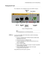
You use the eco-friendly button on the management panel to turn the
LEDs on or off. You can turn off the LEDs when you are not using them to
monitor the control and Ethernet line cards, to conserve electricity. When
the LEDs are off, the overall power consumption of the switch is slightly
reduced by approximately 2 watts.
The button controls all the port LEDs on the Ethernet line cards and
management panel, except for the L/A LED for the NET MGMT port. The
button does not control the LEDs on power supply systems.
Reset Button
Pressing the Reset button resets all the Ethernet line cards in the switch.
You might perform this function if the switch and line cards are
experiencing a problem.
The chassis is booting up.
The chassis has encountered a fault condition.
The chassis is operating as a stand-alone switch, with the
ID number 1.
The chassis is a member of a VCStack and has
The dot in the lower right corner flashes when the switch
accesses USB memory.
an ID number in the range of 1 to 4.
Summary of Contents for AT-FAN08
Page 10: ...Figures 10...
Page 12: ...Tables 12...
Page 16: ...Preface 16...
Page 38: ...Chapter 1 Overview 38...
Page 60: ...Chapter 2 Virtual Chassis Stacking 60...
Page 82: ...Chapter 4 Installing the Chassis 82 Figure 34 Example of Adjusting the Equipment Rack Brackets...
Page 104: ...Chapter 4 Installing the Chassis 104...
Page 140: ...Chapter 5 Powering On the Chassis 140...
Page 166: ...Chapter 7 Cabling the AT XEM2 Line Card Ports 166...


