Chapter 8: Powering On and Verifying the Stack
170
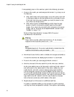
To sequentially power on the switches, perform the following procedure:
1. Power on the switch you want assigned ID number 1, by doing one of
the following
If the switch has an AC power supply, connect the AC power cord
to the power supply on the back panel and to an AC power source.
if the switch has two power supplies, you need to power on only
one of them for this procedure.
If the switch has the AT-SBxPWRSYS1-80 DC Power Supply,
power on the DC circuit and the On/Off switch on the power
supply. (If you have not yet wired the DC connector on the power
supply, refer to “Powering On AT-SBxPWRSYS1-80 DC Power
Supplies” on page 110.)
Refer to “Power Specifications” on page 209 for the power
specifications of the switches.
Warning
Power cord is used as a disconnection device. To de-energize
equipment, disconnect the power cord.
E3
Note
Pluggable Equipment. The socket outlet shall be installed near the
equipment and shall be easily accessible.
E5
2. Wait three minutes for the switch to initialize its management software.
The switch should now be displaying the number 1 on its ID LED.
3. Power on the switch you want assigned the ID number 2.
4. Wait four minutes for the new switch to join the stack as a member.
As the new switch boots up, the first switch, which has the ID number 1
and at this point is the master switch of the stack, notifies the new
switch that its current ID number is already being used and that it
should change its number to the next available number, which is 2.
The new switch automatically changes its ID number to 2 and reboots.
So the new switch is booting up twice, once with the ID number 1 and
again with its new ID number 2, which is why it takes four minutes
before the device becomes a full member of the stack.
5. Repeat steps 3 and 4 to power on additional switches.
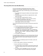
The stack is operational after you have powered on all the switches
and they have been assigned ID numbers. The switches automatically
Summary of Contents for AT-FAN08
Page 10: ...Figures 10...
Page 12: ...Tables 12...
Page 16: ...Preface 16...
Page 38: ...Chapter 1 Overview 38...
Page 60: ...Chapter 2 Virtual Chassis Stacking 60...
Page 82: ...Chapter 4 Installing the Chassis 82 Figure 34 Example of Adjusting the Equipment Rack Brackets...
Page 104: ...Chapter 4 Installing the Chassis 104...
Page 140: ...Chapter 5 Powering On the Chassis 140...
Page 166: ...Chapter 7 Cabling the AT XEM2 Line Card Ports 166...

