Chapter 6: Configuring Switches for Stacking
152
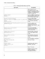
awplus# write
Building configuration ...
[OK]
awplus#
Enter the WRITE command to
save your change.
If this is the initial management
session of the switch, the WRITE
command automatically adds to
flash memory a new configuration
file called DEFAULT.CFG to store
your configuration change. You
can change the name of the file or
designate a different file after you
create the stack.
awplus# reboot
reboot system? (y/n):
awplus#
Restart the switch with the
REBOOT command
Type “Y” for yes.
Wait three minutes for the switch to
initialize its management software.
Check the ID LED and do one of
the following:
- If the ID LED is displaying a
number from 1 to 4, VCStack is
now enabled on the switch. Go to
the next step.
- If the ID LED is still displaying “0,”
repeat this procedure. Be sure to
issue the WRITE command to
save your change.
Go to “Designating Trunk Ports” on
page 153:
Table 13. Commands for Enabling the VCStack Feature (Continued)
Command
Description
Summary of Contents for AT-FAN08
Page 10: ...Figures 10...
Page 12: ...Tables 12...
Page 16: ...Preface 16...
Page 38: ...Chapter 1 Overview 38...
Page 60: ...Chapter 2 Virtual Chassis Stacking 60...
Page 82: ...Chapter 4 Installing the Chassis 82 Figure 34 Example of Adjusting the Equipment Rack Brackets...
Page 104: ...Chapter 4 Installing the Chassis 104...
Page 140: ...Chapter 5 Powering On the Chassis 140...
Page 166: ...Chapter 7 Cabling the AT XEM2 Line Card Ports 166...


