Chapter 8: Powering On and Verifying the Stack
172
Powering On the Switches Simultaneously
If you want the switches to automatically assign the ID numbers
themselves using their MAC addresses during the initial power-on
sequence, you can power them on simultaneously. Here are the steps the
switches perform:
They initialize their management software and compare their MAC
addresses.
The switch with the lowest address is designated as the master
switch of the stack.
The master switch assigns itself the ID number 1.
The master switch assigns ID numbers to the other switches,
which become member switches of the stack.
The member switches reset and initialize their management
software again, with their new ID numbers.
The entire process takes about four minutes. This procedure assumes the
following:
This is the initial power-on sequence of the stack.
You configured the switches for stacking, as explained in Chapter
6, “Configuring Switches for Stacking” on page 141.
The switches are connected with a stack trunk. For background
information, refer to “Stacking Guidelines” on page 41. For cabling
instructions, refer to Chapter 7, “Cabling the AT-XEM2 Line Card
Ports” on page 157.
The switches are powered off.
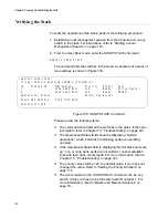
To monitor the power on sequence, you can connect a terminal or PC with
a terminal emulator program to the Console port on either of the switches.
The messages are found in “Monitoring the Initialization Processes” on
page 137.
To have the switches automatically assign the ID numbers, perform the
following procedure:
1. Power on all the switches in the stack at the same time.
To power on switches, do of the following:
For switches with AC power supplies, connect the AC power cords
to the power supply connectors on the back panel and to AC power
sources.
For switches with AT-SBxPWRSYS1-80 DC Power Supplies,
power on the DC circuit and the On/Off switch on the power
Summary of Contents for AT-FAN08
Page 10: ...Figures 10...
Page 12: ...Tables 12...
Page 16: ...Preface 16...
Page 38: ...Chapter 1 Overview 38...
Page 60: ...Chapter 2 Virtual Chassis Stacking 60...
Page 82: ...Chapter 4 Installing the Chassis 82 Figure 34 Example of Adjusting the Equipment Rack Brackets...
Page 104: ...Chapter 4 Installing the Chassis 104...
Page 140: ...Chapter 5 Powering On the Chassis 140...
Page 166: ...Chapter 7 Cabling the AT XEM2 Line Card Ports 166...


