


Appendix A: Technical Specifications
94
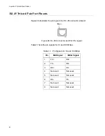
RJ-45 Twisted Pair Port Pinouts
Figure 46 illustrates the pin layout of an RJ-45 connector and port.
Figure 46. RJ-45 Connector and Port Pin Layout
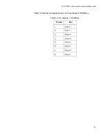
Table 17 lists the pin signals for 10 and 100 Mbps.
Table 17. Pin Signals for 10 and 100 Mbps
Pin
MDI Signal
MDI-X Signal
1
TX+
RX+
2
TX-
RX-
3
RX+
TX+
4
Not used
Not used
5
Not used
Not used
6
RX-
TX-
7
Not used
Not used
8
Not used
Not used
Summary of Contents for AT-DC2552XS
Page 1: ...613 002097 Rev A AT DC2552XS L3 ENTERPRISE CORE SWITCH Installation Guide...
Page 8: ...Figures 8...
Page 10: ...Tables 10...
Page 14: ...Preface 14...
Page 34: ...Chapter 1 Overview 34...
Page 44: ...Chapter 2 VCStack Overview 44...
Page 86: ...Chapter 7 Managing the Switch 86...
Page 90: ...Chapter 8 Troubleshooting 90...