


Chapter 4: Installing the Switch and Modules
58
This procedure requires the following items:
Eight bracket screws (included with the switch)
Two equipment rack brackets (included with the switch)
Cross-head screwdriver (not provided)
Four standard equipment rack screws (not provided)
Perform this procedure to install the switch in a 19-inch equipment rack:
Note
If you have installed the rubber feet, remove the rubber feet by
prying them off the bottom of the chassis with a flat-bladed tool.
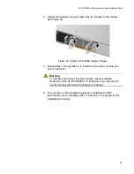
1. Secure the two rack mount brackets to the sides of the switch using
the eight bracket screws provided. Figure 22 shows an example of
mounting the rack mount bracket on the rear of the chassis and with
the bracket flush to the rear panel. See Figure 21 on page 57 for other
possible bracket mounting positions on the chassis.
Figure 22. Attaching the Brackets to Switch
Caution
The chassis may be heavy and awkward to lift. Allied Telesis
recommends that you get assistance when mounting the chassis in
an equipment rack.
E28
Summary of Contents for AT-DC2552XS
Page 1: ...613 002097 Rev A AT DC2552XS L3 ENTERPRISE CORE SWITCH Installation Guide...
Page 8: ...Figures 8...
Page 10: ...Tables 10...
Page 14: ...Preface 14...
Page 34: ...Chapter 1 Overview 34...
Page 44: ...Chapter 2 VCStack Overview 44...
Page 86: ...Chapter 7 Managing the Switch 86...
Page 90: ...Chapter 8 Troubleshooting 90...