


AT-DC2552XS / L3 Enterprise Core Switch Installation Guide
19
AT-DC2552XS/
L3 Physical
Description
The AT-DC2552XS / L3 Enterprise Core Switch physical description is as
follows:
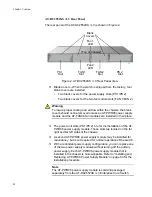
AT-DC2552XS / L3 Front Panel
The front panel of the AT-DC2552XS / L3 is shown in Figure 1.
Figure 1. AT-DC2552XS / L3 Front Panel
Exhaust Air Vents - Air is forced through the chassis by the fan
modules and power supply modules and exits through the exhaust
air vents on the top of the front panel.
Warning
Keep the exhaust air vents clear of any obstructions to insure proper
cooling of the switch components.
SFP+ Slots - There are 48 SPF+ slots (ports 1 - 48) on the front
panel. Each port supports communication speeds up to 10Gbps.
The switch supports a variety of 10G SFP+ transceivers and direct
attach cables.
The AT-DC2552XS / L3 Enterprise Core Switch only supports
SFP+ transceivers in this product. Refer to “Installing SFP+
Transceivers and Cables” on page 68 for installation instructions of
the SFP+ transceivers.
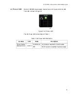
NET MGMT Port LEDs
NET MGMT Port
4 QSFP+ Slots
QSFP+ Slot LEDs
Console Port
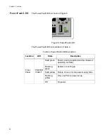
Power/Fault LED
48 SFP+ Slots
SFP+ Slot LEDs
Exhaust Air Vents
[Top of Chassis]
(Ports 1 - 48)
(Ports 49 - 64)
(ETH0)
Summary of Contents for AT-DC2552XS
Page 1: ...613 002097 Rev A AT DC2552XS L3 ENTERPRISE CORE SWITCH Installation Guide...
Page 8: ...Figures 8...
Page 10: ...Tables 10...
Page 14: ...Preface 14...
Page 34: ...Chapter 1 Overview 34...
Page 44: ...Chapter 2 VCStack Overview 44...
Page 86: ...Chapter 7 Managing the Switch 86...
Page 90: ...Chapter 8 Troubleshooting 90...