


Chapter 1: Overview
24
LEDs
Here are the descriptions of the switch’s LEDs.
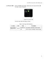
SFP+ Slot LED
Each SFP+ slot has one Link/Activity LED. The LED is triangular in shape.
The triangle LED pointing up shows the status of the upper SFP+ slot
while the triangle LED pointing down shows the status of the lower SFP+
slot. These SFP+ slot LEDs are shown in Figure 3.
Figure 3. SFP+ Slot LEDs
The SFP+ slot LEDs are described in Table 2.
Table 2. SFP+ Slot LED
LED
State
Description
Link/Activity
Solid green
The SFP+ transceiver has established a
link to a network device.
Flashing
green
The SFP+ transceiver is receiving or
transmitting packets to a network device.
Off
The SFP+ slot is empty or the SFP+
transceiver has not established a link to a
network device.
LED Upper
L/A LED
Lower SFP+
Slot
Upper SFP+
Slot
Summary of Contents for AT-DC2552XS
Page 1: ...613 002097 Rev A AT DC2552XS L3 ENTERPRISE CORE SWITCH Installation Guide...
Page 8: ...Figures 8...
Page 10: ...Tables 10...
Page 14: ...Preface 14...
Page 34: ...Chapter 1 Overview 34...
Page 44: ...Chapter 2 VCStack Overview 44...
Page 86: ...Chapter 7 Managing the Switch 86...
Page 90: ...Chapter 8 Troubleshooting 90...