


26
PRATIK - Installation use and maintenance ENG- EDITION: 2018-07-05
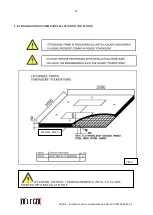
5.2
FOUNDATIONS
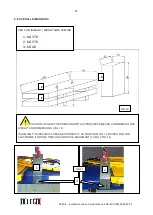
In all lift versions, runways shall be laid onto a reinforced concrete layer class "RcK 30" (30N/mm²) with a
min.thickness of 15 centimetres. The concrete platform shall be smooth and perfectly levelled in all directions, and
cast on a compact ground. Cover the cables and the piping with the metal ducts coming as lift outfit. (
SEE
DRAWINGS FIG. 5 – 5A)
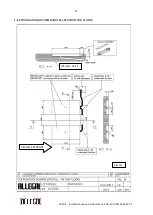
5.3
LIFT POSITIONING
OPERATIONS TO BE CARRIED OUT FOR LIFT INSTALLATION
•
Set runways as shown in Figure 2 or 3, in the immediate vicinity of their installation position, complying with
thedistances specified in Fig. 2.
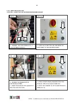
• Lift the runaways one by one and position them on the floor in the designed position, hooking through
suitable lifting systems to the dedicated clamp supplied with the lift (1 and 2 Fig. 14)
, already mounted on
the bases of the lift. Once this operation has been completed, unscrew the screws (3 Fig. 14)to take
away the clamps from the bases and put back the screws in their previous holes without the clamps.
Repeat the same operations also for the other platform.
to the two slots present in the bases (3 and 4 Fig. 14)
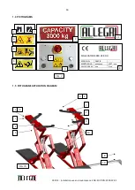
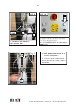
• Extract the fexible pipes from their temporary housings in the footboards. • Place the control unit (10 Fig.
7A) in the nearby of the footboard P1 as shown in Fig. 2 and 3, keeping in mind that the control unit is either
positioned on the left side with respect to the platform P1. To place the unit booby right side of the platform
P1, refer to Figures 15 and 15A..
• The lift is supplied tested with the pipes arranged to the control unit positioned on the left side of the
platform P1 with respect to the input side of the vehicle as shown in Fig. 15A
If the installation of the lif takes place in the pit instead of on the floor, complete the installation
in a similar way as just described, making sure to place the entire structure of the lift in a
centered position with respect was the same.
.
After placing the platforms in the connections:.
-
HYDRAULIC
-
ELECTRICAL
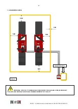
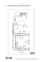
5.4 CONNECTING HYDRAULIC PIPES (SEE SCHEME IN FIG. 15 and 15A)
CAUTION: It is very important to properly perform the hydraulic system and its connections.
Therefore, follow all instructions below carefully. After placing the control unit (10 fig.7a) as shown
in the diagram in Figures 2 and 3, you must:
• Open the cover of the unit by unscrewing the screws on the sides. • Remove the caps, used to prevent oil
spills or impurities entrance, placed on hoses and proceed to their connection to the respective connections
in the control unit.
WARNING: When removing the caps of the pipes it is possible to have small oil spills; therefore,
place on the floor an appropriate container to collect the oil
Summary of Contents for PRATIK 30
Page 2: ...2 PRATIK Installation use and maintenance ENG EDITION 2018 07 05...
Page 3: ...3 PRATIK Installation use and maintenance ENG EDITION 2018 07 05...
Page 4: ...4 PRATIK Installation use and maintenance ENG EDITION 2018 07 05...
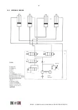
Page 37: ...37 PRATIK Installation use and maintenance ENG EDITION 2018 07 05 8 0 HYDRAULIC SCHEME...
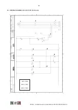
Page 38: ...38 PRATIK Installation use and maintenance ENG EDITION 2018 07 05...
Page 42: ...42 PRATIK Installation use and maintenance ENG EDITION 2018 07 05...
Page 44: ...44 PRATIK Installation use and maintenance ENG EDITION 2018 07 05...
Page 53: ...53 PRATIK Installation use and maintenance ENG EDITION 2018 07 05 TAV 3 CONTROL UNIT...