


24
PRATIK - Installation use and maintenance ENG- EDITION: 2018-07-05
•
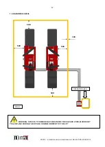
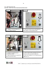
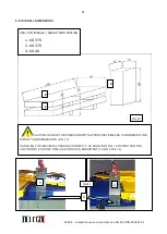
Place the four arms with rubber thicknesses (4-5 Fig.1B) at the points provided for lifting as indicated by
the car manufacturer
•
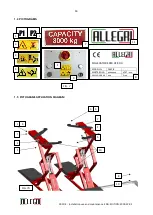
Check that the switch disconnect (10 Fig.1A) is ON (1); if it is not, turn it on. • Raise the vehicle by 10
centimeters.
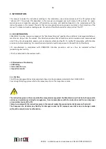
Check the stability of the vehicle.
• Proceed to lifting the vehicle.
• Turn the key-switch (10 Fig. 1A) in the OFF position (0) before access to the platforms of the lift.
4.3
VEHICLE LOWERING AND UNLOADING PROCEDURE
•
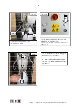
For vehicle lowering and unloading, proceed as follows:
•
Check that the Emergency/OFF Switch/Disconnector (11, Fig. 1) is set to "ON" (turn it on, if necessary).
• Press the down button (12 Fig. 1A) and bring down the platforms; an intermittent acoustic signal will be
activated to indicate the risk during all this phase. The operator must ensure that:
DANGER!
Check that inside the danger area bounded by the yellow band (Fig. 8) there are no
people or animals. The above verifcation must always be made before proceeding with the
lowering of the lift, because this phase is considered to be particularly hazardous for any people
who are nearby the risk areas (Fig. 8).
Turn the key-switch (10 Fig. 1A) to the OFF position (0).
• Remove the four arms with rubber pads (4-5 Fig.1A). and bring them to rest in their position.
• Pull down the vehicle by the platforms.
4.4
SAFETY DEVICES
WARNING: The following safety devices must never be tampered with or excluded, are also
always kept in good state of efficiency:
• Hydraulic system by transfer with jacks to keep runways aligned during the up/down movements.
• System for runway alignment at maximum height with alignment valve and air bleeding.
• Switch/Disconnector (10, Fig. 1A): if turned to OFF (0), it stops lift operation.
• Voltage warning light (13, Fig. 1A): when it is on, panel is powered and it is not allowed to reach under the
runways.
• Low-voltage additional electric circuit: this circuit cannot originate any electric shock.
• Rubber pads (6, Fig. 1B): they ensure lifted vehicle grip onto runways.
Summary of Contents for PRATIK 30
Page 2: ...2 PRATIK Installation use and maintenance ENG EDITION 2018 07 05...
Page 3: ...3 PRATIK Installation use and maintenance ENG EDITION 2018 07 05...
Page 4: ...4 PRATIK Installation use and maintenance ENG EDITION 2018 07 05...
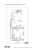
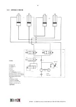
Page 37: ...37 PRATIK Installation use and maintenance ENG EDITION 2018 07 05 8 0 HYDRAULIC SCHEME...
Page 38: ...38 PRATIK Installation use and maintenance ENG EDITION 2018 07 05...
Page 42: ...42 PRATIK Installation use and maintenance ENG EDITION 2018 07 05...
Page 44: ...44 PRATIK Installation use and maintenance ENG EDITION 2018 07 05...
Page 53: ...53 PRATIK Installation use and maintenance ENG EDITION 2018 07 05 TAV 3 CONTROL UNIT...