Steps
1. Lay the computer on the right side.
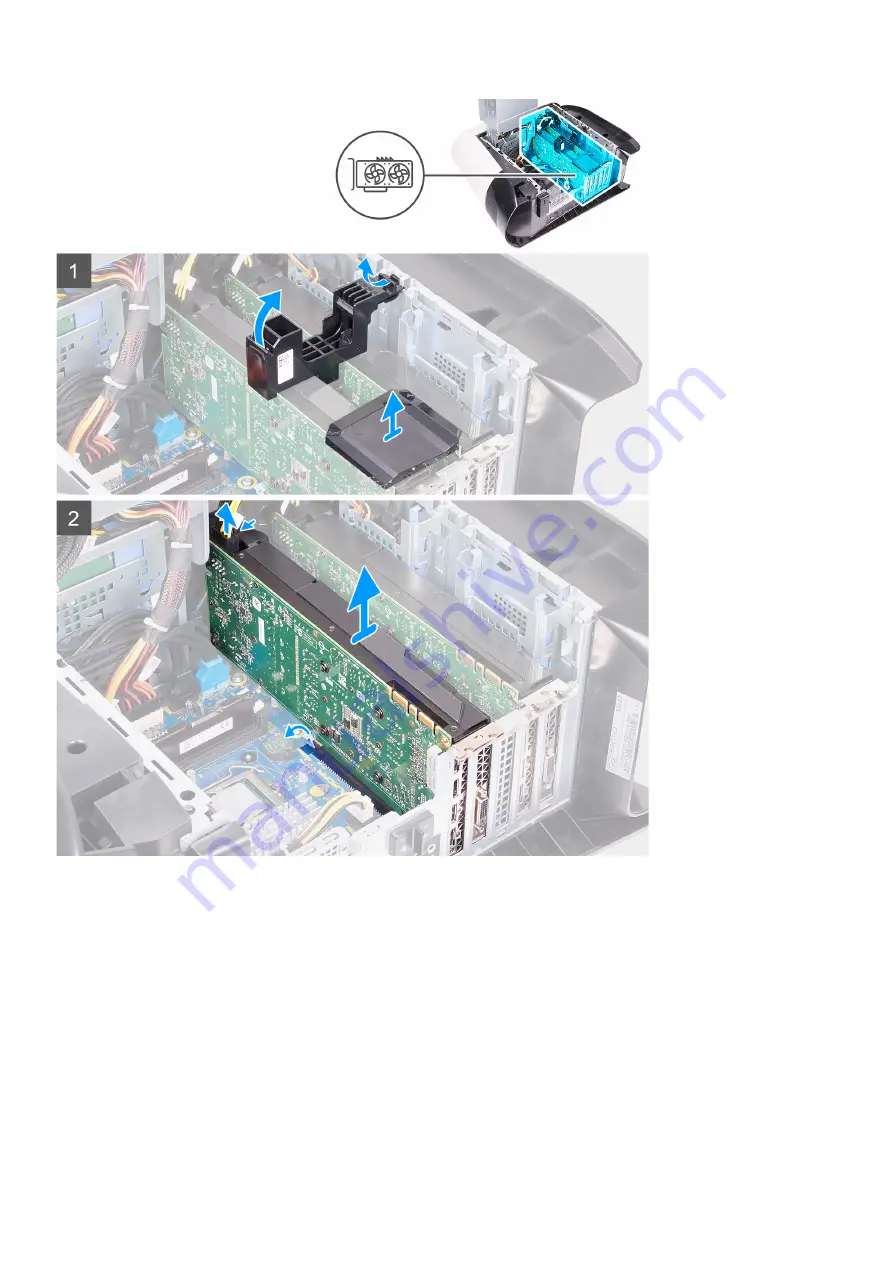
2. Press the releasing clip on the power-cable connectors and disconnect the power cables from the graphics card.
3. Slide the power-supply unit cage release latches to the unlock position.
4. Lift the power-supply unit cage and rotate the power-supply unit cage away from the chassis.
5. Lift the graphics bridge that connects the graphics cards.
6. Lift to release the graphics-card bracket from the chassis.
7. Press the releasing clip on the power-cable connectors and disconnect the power cables from the graphics card.
8. Push the securing tab on the PCIe slot away from the graphics card, grasp the card by its top corner, and ease it out of the slot on
the PCI-Express x8 slot.
9. Push the securing tab on the PCIe slot away from the graphics card, grasp the card by its top corner, and ease it out of the slot on
the PCI-Express x16/x8 slot.
54
Summary of Contents for Aurora R11
Page 1: ...Alienware Aurora R11 Service Manual Regulatory Model D23M Regulatory Type D23M002...
Page 17: ...17...
Page 20: ...NOTE Note the orientation on the hard drive carrier to replace it correctly 20...
Page 23: ...NOTE Note the orientation on the hard drive carrier to replace it correctly 23...
Page 28: ...28...
Page 45: ...Steps 1 Ensure that the securing clips are extended away from the memory module slot 45...
Page 49: ...49...
Page 51: ...51...
Page 56: ...56...
Page 59: ...59...
Page 62: ...62...
Page 63: ...63...
Page 71: ...71...
Page 83: ...Steps 1 Lay the computer on the right side 83...
Page 92: ...92...


