Air Monitor VELTRON II Installation, Operation And Maintenance Manual Download Page 69

VELTRON II

Air Monitor Corporation

116-011-98.P65   (8/30/10)

VELTRON II - IO&M Manual
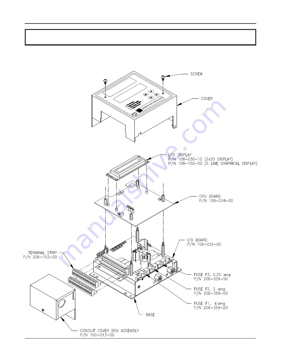
9 – PARTS LIST

The following drawing with part numbers lists components of the VELTRON II that are easily replaced by the user.
When contacting the Customer Service Department about parts, please have the applicable Factory Set-Up Information
sheet available for reference. To inquire about price and availability of a specific part number, please contact the
Customer Service Department at:

Phone: 707-544-2706

800-AIRFLOW

Fax:

707-526-2825

64

SECTION 9 – PARTS LIST

Summary of Contents for VELTRON II

Page 1: ...er Versions 5 3X Installation Operation Maintenance Air Monitor Corporation provides complete technical support between the hours of 7 a m and 5 p m PST M F Contact our Service Department Toll Free 1 800 AIRFLOW or fax us at 1 707 526 2825 Air Monitor Corporation 116 011 98 P65 8 30 10 VELTRON II IO M Manual ...

Page 2: ......

Page 3: ... PRESSURE CALCULATOR 5 3 10 NETWORK 5 3 11 MULTIPLE OPERATING POWER SELECTIONS 5 3 12 ENCLOSURE 5 SECTION 4 INSTALLATION 4 1 RECEIVINGAND INSPECTION 6 4 2 LOCATION 6 4 3 MOUNTING 6 4 4 PROCESS CONNECTIONS 7 4 5 POWER SIGNAL CONNECTIONS 8 9 4 6 INPUT OUTPUTSELECTION 10 4 7 DISPLAY CONTRASTADJUSTMENT 10 SECTION 5 OPERATION 5 1 INTRODUCTION 11 5 2 START UP 11 5 3 NORMALOPERATION 12 5 4 CONFIGURATION ...

Page 4: ...ATION 47 5 22 TRANSMITTEROUTPUTCALIBRATION 47 5 23 POWER SUPPLY CALIBRATION 48 5 24 TRANSDUCERCHARACTERIZATIONSELECTION 49 5 25 NETWORK CONFIGURATION 50 5 26 MENU INACTIVITY TIMEOUT SELECTION 51 SECTION 6 CALIBRATION 6 1 REQUIRED EQUIPMENT 52 6 2 PREPARATION 52 6 3 TRANSMITTERINPUTCALIBRATION 53 58 6 4 TRANSMITTEROUTPUTCALIBRATION 59 60 SECTION 7 MAINTENANCE 61 SECTION 8 TROUBLESHOOTING 62 63 SECT...

Page 5: ...of instructions furnished by Seller nor does it extend to any product which has been repaired or altered by persons not expressly approved by Seller Nor does Seller warrant equipment against normal deterioration due to environment nor items such as lamps glass and similar items subject to wear or burnout through usage Adjustments for items or equipment not manufactured by Seller shall be made to t...

Page 6: ...probes or static pressure sensors act upon opposite sides of a flexible diaphragm within the transducer The differential between the two pressure signals displaces the diaphragm the magnitude of the displacement being measured creates an electrical DC output from the transducer After undergoingA D conversion the resulting digital signal representing differential pressure or velocity pressure can b...

Page 7: ... Ranges Natural Spans Bi Polar Natural Spans 0 to 25 00 IN w c 0 to 10 00 IN w c 10 00 to 10 00 IN w c 0 to 5 00 IN w c 5 00 to 5 00 IN w c 0 to 2 00 IN w c 2 00 to 2 00 IN w c 0 to 1 00 IN w c 1 00 to 1 00 IN w c 0 to 0 50 IN w c 0 50 to 0 50 IN w c 0 to 0 25 IN w c 0 25 to 0 25 IN w c 0 to 0 10 IN w c 0 10 to 0 10 IN w c 0 to 0 05 IN w c 0 05 to 0 05 IN w c Span Rangeability The calibrated span ...

Page 8: ...ive LED flashing at a rate of one time per second 3 3 AUTOMATIC ZEROING At periodic intervals the microprocessor will automatically execute an AUTO zero cycle consisting of the following sequence The transmitter output and display signals are put on Hold a valve is activated which disconnects the process high pressure from the high port of the transducer and connects the process static pressure to...

Page 9: ...rocess Signal High2Alarm Point Point Process Signal Low1 Alarm High1Alarm Point Point Low Alarm Low2 Alarm Process Point Point Signal Low High Alarm Low1 Low2 Alarm High1 High2 Alarm 3 6 SPECIAL FUNCTIONS option When used in conjunction with an external input second transmitter applied to the special function input terminals the VELTRON II can perform one of the Special Functions listed below With...

Page 10: ...two types of applications 1 To adjust for flow measurement error as a result of highly distorted airflow induced by upstream or downstream flow disturbances 2 To adjust the transmitter s output to bring it into close correlation with field measured flow data The K Factor gain and bias values can be entered directly or the VELTRON II can calculate these values based on measured and reference values...

Page 11: ...1 enclosure which provides some degree of protection which is sufficient for most clean indoor locations Where additional protection is deemed necessary the VELTRON II should be mounted in an enclosure with adequate NEMA rating The ambient temperature of the selected mounting location must be between 40º 140ºF Consideration should be given to units installed in enclosures exposed to direct sunligh...

Page 12: ...tions must be completed as follows High Port on VELTRON II connects to reference sensor Low Port on VELTRON II connects to sensor from monitored room Although any size of tube pipe can be used the response time of the VELTRON II to process change increases with increasing tube pipe size or increasing in tube pipe length CAUTION Selected fittings should be compatible with the brass 1 8 FPT bulkhead...

Page 13: ...ge that the terminal strip can accommodate No more than two wires should be connected to any one terminal 18 awg is the maximum gauge wire that can be doubled up in one terminal To facilitate wiring and any future removal of the VELTRON II each terminal strip is removable from the unit Remove terminal strip marked 1 16 first by pulling sideways away from the unit A flat blade screwdriver can also ...

Page 14: ... source polarity must be maintained Purge Interrupt Terminals 17 and 18 Customer to provide momentary 0 5 to 10 seconds unpowered dry contact to interrupt a purge cycle in progress AUTO purge Purge Valves SV 1A SV 1B or Alarm 1 Terminals 21 22 and 23 ForAUTO purge Option Customer to connect terminals 21 and 22 toAUTO purge panel terminal 23 not used Contacts close uponAUTO purge cycle initiation r...

Page 15: ...output remove all jumpers from the present signal type pins and install them on the desired signal type pins Inputs have a single jumper covering two pins and outputs have two jumpers covering four pins 4 7 DISPLAY CONTRAST ADJUSTMENT To compensate for different ambient lighting conditions and viewing angles the VELTRON II display s contrast can be adjusted for optimum visibility Contrast is adjus...

Page 16: ...g 5 2 START UP 1 After Installation has been verified in accordance with Section 4 turn power switch located at the lower front side to the ON position see Figure 4 1 2 Display will briefly indicate VELTRON II with the progressing from left to right Followed by PerformingAuto Zero with the progressing from left to right After approximately 10 seconds the unit will return to Normal display mode and...

Page 17: ...ctivated display will be frozen and all outputs will remain constant During this cycle the AUTO purge In Progress LED will remain lit Length of cycle depends on purge duration and after purge duration see Factory Set Up Information Sheet This cycle will not occur if AUTO purge has been turned OFF in configuration programming see Section 5 11 The AUTO purge cycle can be manually activated by user i...

Page 18: ...n mode This is accomplished using the four pushbuttons located on the VELTRON II s top cover The type i e 4 20mA 0 5V 0 10V of available outputs can also be changed by jumper selections on I O Board see Section 4 6 To gain access to the jumpers remove two 10 32 screws on front cover and pull the cover straight up and swing to the right CAUTION With cover removed ESD electrostatic discharge precaut...

Page 19: ...up UP or DN Use to scroll to the desired Main Menu item Use to scroll to the value or mode within a Parameter ENT Enters user into specific selection sub menu from Main Menu Selection Displays current setting of selected Parameter Enters the selected value or mode into memory ESC Use to exit Main Menu selection to avoid scrolling to Return to MAIN MENU The following pushbutton combinations can be ...

Page 20: ...he factory The following will detail all user parameters which may or may not be available on your unit With power ON and initialization complete see Section 5 2 simultaneously press ESC and ENT and display will indicate OPERATOR SETUP Pressing ENT again will enter the user into the Main Menu of configuration programming The display will indicate Operator Password Selection Refer to next page for ...

Page 21: ...nt of filtering applied to transducer output Turns AUTO zero function ON or OFF and selects interval Turns AUTO purge function ON or OFF and selects internal external activation interval purge duration after purge time Not installed with VELTRON II Turns alarm function ON or OFF select Alarm Type High and Low Setpoints Deadband selection and Alarm Delay Not installed with VELTRON II Turns Special ...

Page 22: ...All selections that are available for further configuration programming will have an arrow symbol displayed in the right side of the display field Those that are not available for further configuration programming will not have the arrow symbol displayed and will display Not Installed beneath the selection description Example Auto Purge Not Installed The remainder of this Section details steps to ...

Page 23: ...NT New password will be stored in memory and display will return to Operator Password Selection menu as in Step 2 Note If user desired not to change the password and return to Operator Password Selection menu press ESC Unit will remain programmed as it was originally 5 Use UP or DN to select remaining parameters to be changed 6 Follow Step 4 to make any changes to parameters 7 To return to Main Me...

Page 24: ...On Selection Square Root Off On ON EXIT Process Configuration Transmitter Flow or Transmitter Velocity Process Type Selection 2 Process Type TRANSMITTER FLOW See UNITS list for available selections Process Units Selection Process Units FLOW CFM See FORMAT list for available selections Process Format Selection Process Format FLOW XX XXX CFM Depends on Process Type and Format Process Minimum Selecti...

Page 25: ...to the Process Configuration sub menu press ESC Unit will remain programmed as it was originally 6 Use UP or DN to select remaining parameters to be changed within the Process Configuration sub menu See the follow Units Lists for the available Process Units selections for the appropriate Process Type See the following Format List for the available Process Format selections 7 Follow Step 5 to make ...

Page 26: ... OF MEASUREMENT DISPLAY feet per second feet per minute feet per hour meters per second meters per minute meters per hour Actual feet per second Actual feet per minute Actual feet per hour Actual meters per second Actual meters per minute Actual meters per hour Standard feet per second Standard feet per minute Standard feet per hour Standard meters per second Standard meters per minute Standard me...

Page 27: ... feet per minute Actual cubic feet per hour Actual liters per second Actual liters per minute Actual liters per hour Actual cubic meters per second Actual cubic meters per minute Actual cubic meters per hour Standard cubic feet per second Standard cubic feet per minute Standard cubic feet per hour Standard liters per second Standard liters per minute Standard liters per hour Standard cubic meters ...

Page 28: ... column inches of mercury pounds per square inch gauge Pascals kilo Pascals bars millibars millimeter of water column millimeter of mercury kilograms per square meter Percent in WC in Hg psig Pa kPa bars mbars mm WC mm Hg kg m2 FORMAT LIST 0XXXXX 0 XXXXX X XXXX XX XXX XXX XX X XXX X XX XXX XXX XX0 XXXX X00 XXXX 000 0 to 025000 0 to 0 25000 0 to 2 5000 0 to 25 000 0 to 250 00 0 to 2 500 0 0 to 25 0...

Page 29: ... Calculate D P Flow DIFF PRES DIFF PRES or FLOW Calculate D P Flow Selection Diff Pressure 1 000 in WC 0 000 to 25 000 inWC in 0 001 increments Diff Pressure Selection5 Default selection shown Available selections Process Static Pres 0 0 in WC 6 Process Temp 68 F Standard Temp 68 F 295 0 to 1 630 0 in WC in 0 01 increments 50 to 2000 F in 1 increments 0 to 100ºF in 1º increments Calculator For Max...

Page 30: ...ow Value5 Update Operating Span Diff Press Value7 Reset Calculation Default Values EXIT Update Flow NO Update Operating Span NO NO or YES 4 Calculator uses parameters entered in Process Configuration ie Type Max Area Units etc as necessary to perform calculation Steps in this Section marked with indicate values or choices previously made in Process Congiuration Exits to Trans Scaling Configuration...

Page 31: ...perature reads 150ºF 14 Press ENT and scroll to Calculate Diff Pres Value 15 Press ENT and a new value for Differential Pressure will be displayed 16 Press ENT and then UP and display will read Update Operating Span Diff Pres Value 17 Press ENT scroll to YES and press ENT display will return to that shown in Step 16 and new operating span will be stored in memory Note If during this step display i...

Page 32: ...ut 1 While in Main Menu use UP or DN to scroll to Low Pass Filter Selection 2 Press ENT and display indicates current setting of Low Pass Filter 0 none to 8 Maximum 3 Use UP or DN to change setting Once desired setting is displayed press ENT and new setting will be stored in memory and display will return to Main Menu Note If user desires not to change the setting and return to Main Menu press ESC...

Page 33: ...in Menu use UP or DN to scroll to Auto Zero Configuration 2 Press ENT to enter AUTO zero Configuration menu Display will indicate Auto Zero Off On Selection 3 Press ENT and display will indicate current setting of AUTO zero OFF or ON 4 Use UP or DN to change setting Once desired setting is displayed press ENT and new setting will be stored in memory and display will return toAUTO zero Configuratio...

Page 34: ...tion 1 Return to MAIN MENU Operator Setup Main Menu 5 11 AUTO purge CONFIGURATION User can turnAUTO purge function ON or OFF select method of activation activation interval purge duration and after purge duration 1 While in Main Menu use UP or DN to scroll to Auto Purge Configuration 2 Press ENT to enterAUTO purge Configuration menu Display will indicate Auto Purge Off On Selection 3 Press ENT and...

Page 35: ... 011 98 P65 8 30 10 VELTRON II IO M Manual 30 SECTION 5 OPERATION 5 12 AUTO calibration CONFIGURATION Auto purge Configuration Auto Cal Not Installed Alarm Configuration Auto Calibration not installed on Veltron II Operator Setup Main Menu ...

Page 36: ...ondition existing and alarm activation Adjustable between 0 0 and 10 0 minutes in 0 1 minute increments 31 SECTION 5 OPERATION Alarm 1 Off On Selection Alarm 2 Off On Selection Alarm Type Selection Alarm 1 Low 2 Setpt Selection Alarm 2 High3 Setpt Selection Alarm 1 Dead Band Selection Alarm 2 Dead Band Selection Alarm 1 Delay Selection Alarm 2 Delay Selection Return to MAIN MENU Alarm 1 Off On OFF...

Page 37: ...ate Alarm 1 Off On Selection 3 Press ENT and display will indicate current setting of Alarm 1 OFF or ON 4 Use UP or DN to change setting Once desired setting is displayed press ENT New setting will be stored in memory and display will return to Alarm Configuration menu as in Step 2 Note If user desires not to change the setting and return toAlarm Configuration menu press ESC Unit will remain progr...

Page 38: ...n is selected as Function Type Time between an alarm condition existing and alarm activation Adjustable between 0 0 and 10 0 minutes in 0 1 minute increments SECTION 5 OPERATION 33 Default selection shown Available selections Controller Not Installed Special Function Config K Factor Configuration Special Func Off On Selection Function Type Selection Extrnl Input Maximum Selecton Deviation Setpoint...

Page 39: ...f Special Function OFF or ON 4 Use UP or DN to change setting Once desired setting is displayed press ENT New setting will be stored in memory and display will return to Special Function Configuration menu as in Step 2 Note If user desires not to change the setting and return to Special Function Configuration menu press ESC Unit will remain programmed as it was originally 5 Use UP or DN to select ...

Page 40: ...or Exponent Selection 5 K Factor Gain Selection 5 K Factor Bias Selection 5 Display Max D P 2 Return to MAIN MENU K Factor Exponent X XXXX 0 500 to 2 000 0 0001 increments K Factor Configuration Return to MAIN MENU K Factor Off On OFF OFF or ON 1 Not available if Process Type is D P see Transmitter Scaling Config 3 Available only if YES is selected in Calculate K Factor Calculate K Factor NO NO or...

Page 41: ...setting of K Factor OFF or ON 4 Use UP or DN to change setting Once desired setting is displayed press ENT New setting will be stored in memory and display will return to K Factor Configuration menu as in Step 2 Note If user desires not to change the setting and return to K Factor Configuration menu press ESC Unit will remain programmed as it was originally 5 Use UP or DN to select remaining param...

Page 42: ...splay will indicate LINE 2 PARAMETER Selection 6 Press ENT and display will indicate current parameter selected to display on Line 2 see Parameter List in Section 5 18 for available selections K Factor Configuration Standard Display Config Analog Output Configuration 1Not available if Enhanced Display option is purchased 0 None to 4 Maximum Default selection shown Available selections Standard Dis...

Page 43: ... units Use UP or DN to change units and press ENT when desired units are displayed 11 Press UP and display will indicate LINE 2 FILTER Selection Note Filter selection will not be available if selected parameter is ALARM SETPOINT 12 Press ENT and display will indicate current Filter setting selected for Line 2 0 None 1 Minimum 2 3 or 4 Maximum 13 Use UP or DN to scroll to desired filter setting Pre...

Page 44: ...UP and display will indicate Return to MAIN MENU 22 Press ENT to return to Main Menu Note In Set Custom Text mode the pushbuttons can be used in the following combinations to facilitate programming ESC UP Moves position cursor to the right one position at a time ESC DN Moves position cursor to the left one position at a time ESC ENT Exits Set Custom Text Does not enter any changes to the display s...

Page 45: ...NE 4 LINE 5 Return to MAIN MENU LINE 2 PARAMETER DIFF PRES UNITS2 SET CUSTOMTEXT3 FILTER 4 EXIT LINE 1 FILTER EXIT LINE 4 same as LINE 2 LINE 2 Parameter DIFF PRESSURE LINE 2 FILTER 0 None 1 Only with Enhanced Display option see Parameter List for selection for lines 2 3 4 0 None to 4 Maximum Default selection shown Available selections Enhanced Display Config 1 LINE 2 EXIT Return to MAIN MENU LIN...

Page 46: ...ote Filter selection will not be available if selected parameter is ALARM SETPOINT 13 Press ENT and display will indicate current Filter setting selected for Line 2 0 None 1 Minimum 2 3 or 4 Maximum 14 Use UP or DN to scroll to desired filter setting Press ENT and filter setting will be stored in memory and display will indicate as in Step 12 15 Press UP and display will indicate LINE 2 EXIT 16 Pr...

Page 47: ...ble characters 23 When desired character is displayed press ENT character will be stored and cursor will advance one position to the right 24 Repeat Steps 22 and 23 for all 20 positions When position 20 is entered user will be exited back to display as in Step 20 25 Press UP and display will indicate LINE 2 EXIT 26 Press ENT then UP and display will indicate LINE 3 27 Repeat Steps 8 through 16 for...

Page 48: ...le only if Percent Deviation has been selected as a Special Function n Available only if Special Function option has been installed D PRESS VELO SF EXT DEV SUM AVG DELTA DELTA LO SEL HI SEL LO SP HI SP LO1 SP LO2 SP HI1 SP HI2 SP DEV SP Display will indicate process type selected in Process Configuration XX PARAMETER LIST for Lines 2 3 4 and 5 PARAMETER DISPLAY in NORMAL MODE NONE DIFF PRESSURE TR...

Page 49: ... P65 8 30 10 VELTRON II IO M Manual 44 5 18 ENHANCED DISPLAY CONFIGURATION con t SECTION 5 OPERATION 0 1 2 3 4 5 6 7 8 9 A B C D E F G H I J K L M N O P Q R S T U V W X Y Z a b c d e f g h i j k l m n o p q r s t u v w x y z ASCII Character Chart ...

Page 50: ...5 15 4 Use UP or DN to change setting Once desired setting is displayed press ENT New setting will be stored in memory and display will return to Analog Output Configuration menu as in Step 2 Note If user desires not to change the setting and return to Analog Output Configuration menu press ESC Unit will remain programmed as it was originally 5 Use UP or DN to select remaining parameters to be cha...

Page 51: ...desired setting is displayed press ENT New setting will be stored in memory and display will return to Main Menu Caution Only change setting if a transducer of different natural span has been installed Note If user desires not to change the setting and return to Main Menu press ESC Unit will remain programmed as it was originally 5 Use UP or DN to select remaining parameters to be changed 6 Follow...

Page 52: ... Zero 1 Special Function Span 1 Return to MAIN MENU Transducer Span Selection Transmitter Input Calib Transmitter Output Calib Transmitter Input Calib 1Available only with Special Function option See Calibration Instructions Operator Setup Main Menu Output 1 Zero Output 1 Span Output 2 Zero Output 2 Span Output 3 Zero 1 Output 3 Span 1 Output 4 Zero 1 Output 4 Span 1 Return to MAIN MENU See Calibr...

Page 53: ...o scroll to Power Supply Calibration 2 Press ENT and display will indicate current power supply voltage on line 2 Set To 7 000 0 100 7 000 VDC 3 If supply voltage is less than 6 900V or greater than 7 100V adjust R36 on I O Board see Figure 5 2 until acceptable voltage reading is displayed on line 2 4 When done press ENT to return to Main Menu Set to 7 000 0 100 7 000 VDC See Calibration Instructi...

Page 54: ... data be entered This new data along with instructions will be provided with the new transducer from the Factory Power Supply Calibration Xdcr Characterizat n Select Network Selection Data Point 1 Selection Data Point 2 Selection Data Point 3 Selection Data Point 4 Selection Data Point 5 Selection Return to MAIN MENU Xdcr Character Selection Data Point 1 0 Data Point 2 2 500 Data Point 3 5 000 Dat...

Page 55: ...ing and return to Network Configuration menu press ESC Unit will remain programmed as it was originally 5 Use UP or DN to select remaining parameters to be changed 6 Follow Step 4 to make any changes to parameters 7 To return to Main Menu select Return to MAIN MENU in Network Configuration menu and press ENT Network Off On Selection Xmit In Sig Source Selection IP Addr Octet 3 Selection IP Addr Oc...

Page 56: ...display will indicate current timeout value 1 to 30 minutes or OFF 3 Use UP or DN to change timeout value Once desired value is displayed press ENT New setting will be stored in memory and display will return to Main Menu Note If user desires not to change the setting and return to Main Menu press ESC Unit will remain programmed as it was originally Network Selection Menu Inactivity Timeout Select...

Page 57: ...be positioned in the same attitude as in its operating location 6 1 REQUIRED EQUIPMENT 1 Digital Manometer capable of reading to the nearest 0 001 w c 2 Digital Multimeter 3 Source of clean dry instrument air 4 Adjustable low pressure regulator such as AMC Low Pressure Air Source or equal 6 2 PREPARATION 1 Turn Power switch OFF on front of VELTRON II see Figure 4 1 2 Remove Low and High pressure s...

Page 58: ...ay will count down to 0 after which it will indicate Input Zero Done Push ESCAPE 53 Display will count down to 0 after which it will indicate Input Span Done Push ESCAPE Note If pressure input is less than 40 or greater than 110 of transducer s natural span value see Factory Set Up Information Sheet display will indicate Bad Input Span Push ESCAPE If this occurs check input pressure as read on man...

Page 59: ...Zero Settle Time 4 Sec Display will count down to 0 after which it will indicate Input Zero Done Push ESCAPE 15 Press ESC and then UP display will indicate Special Func Span Calib Aux 2 Maximum 16 Press ENT and display will indicate Special Func Span Push ENTER 17 With voltage current generator still connected as in Step 12 adjust to maximum value of Special Function input see Factory Set Up Infor...

Page 60: ...splay will count down to 0 after which it will indicate Input Span Done Push ESCAPE 55 5 Press ESC and then UP display will indicate Transducer Span Calib X XX in WC 6 Apply input pressure as read on manometer to the High port of the VELTRON II Adjust pressure to equal the transducer natural span value which is indicated on the display 7 Press ENT and display will indicate Transducer Span Push ENT...

Page 61: ...Zero Settle Time 4 Sec Display will count down to 0 after which it will indicate Input Zero Done Push ESCAPE 15 Press ESC and then UP display will indicate Special Func Span Calib Aux 2 Maximum 16 Press ENT and display will indicate Special Func Span Push ENTER 17 With voltage current generator still connected as in Step 12 adjust to maximum value of Special Function input see Factory Set Up Infor...

Page 62: ...r Zero Push ENTER 6 Press ENT and display will indicate Transducer Zero Settle Time 4 Sec Display will count down to 0 after which it will indicate Input Zero Done Push ESCAPE 57 7 Press ESC and then UP display will indicate Transducer Span Calib X XX in WC 8 Apply input pressure as read on manometer to the High port of the VELTRON II Adjust pressure to equal the transducer natural span value whic...

Page 63: ... Zero Settle Time 4 Sec Display will count down to 0 after which it will indicate Input Zero Done Push ESCAPE 18 Press ESC and then UP display will indicate Special Func Span Calib Aux 2 Maximum 19 Press ENT and display will indicate Special Func Span Push ENTER 20 With voltage current generator still connected as in Step 15 adjust to maximum value of Special Function input see Factory Set Up Info...

Page 64: ...he actual process load DMM should be reading minimum value 0 00 0 01 volts or 4 00 0 01mA 5 If DMM is reading out of tolerance use UP or DN to adjust VELTRON II output for an acceptable DMM reading Depending on DMM s selected range the UP or DN button may need to be pressed and held for a period of time before any change occurs in the DMM s display To speed up changes in output pushbutton combinat...

Page 65: ...M is reading out of tolerance use UP or DN to adjust VELTRON II output for an acceptable DMM reading 10 Once an acceptable span reading is obtained press ENT and then UP and display will indicate Output 2 Zero 11 Repeat Steps 3 through 10 for Transmitter Output 2 andAnalog Output 3 and 4 if available For Transmitter Output 2 connect DMM across terminals 2 and 3 for Analog Output 3 across terminals...

Page 66: ...f specific types of maintenance 7 1 CLEANLINESS Periodically inspect VELTRON II for build up of dust and debris Keep field wiring terminal strips clean to preclude shorting between terminals Verify condensation or other sources of liquids are not present inside the VELTRON II 7 2 MECHANICAL Verify pressure signal connections are secure Inspect pressure signal lines for any cracks or leaks Verify m...

Page 67: ...6 Replace I O Board Verify pressure signal lines are connected correctly Check for leaky or obstructed lines between VELTRON II and process sensor Check for kinked internal signal pressure lines in transmitter base Replace Transducer Replace CPU Board Verify correct output is selected see Section 5 19 Verify correct input is applied for process application or special function see Section 4 5 Verif...

Page 68: ...but is not functioning Unreliable is displayed on Line 1 of the display Unable to access Operator Setup Solution Verify AUTO purge is on interval and activation are properly set see Section 5 11 Check for proper terminal strip wiring and connections see Section 4 5 Verify correct wiring to purge panel see Section 4 5 Check Fuse F1 see Figure 5 2 for location Verify that Alarm is ON and setpoints a...

Page 69: ... that are easily replaced by the user When contacting the Customer Service Department about parts please have the applicable Factory Set Up Information sheet available for reference To inquire about price and availability of a specific part number please contact the Customer Service Department at Phone 707 544 2706 800 AIRFLOW Fax 707 526 2825 64 SECTION 9 PARTS LIST ...

Page 70: ... that are easily replaced by the user When contacting the Customer Service Department about parts please have the applicable Factory Set Up Information sheet available for reference To inquire about price and availability of a specific part number please contact the Customer Service Department at Phone 707 544 2706 800 AIRFLOW Fax 707 526 2825 65 SECTION 9 PARTS LIST ...

Page 71: ...ible ensure equipment is packaged sufficiently to protect it during shipment CAUTION All damage occurring during transit is the Customer s responsibility List the Return Authorization R A number on the packing list and clearly mark this number on the outside of each shipping container Costs associated with return of equipment to Air Monitor are the customer s responsibility regardless whether the ...

Reviews: