background image

8

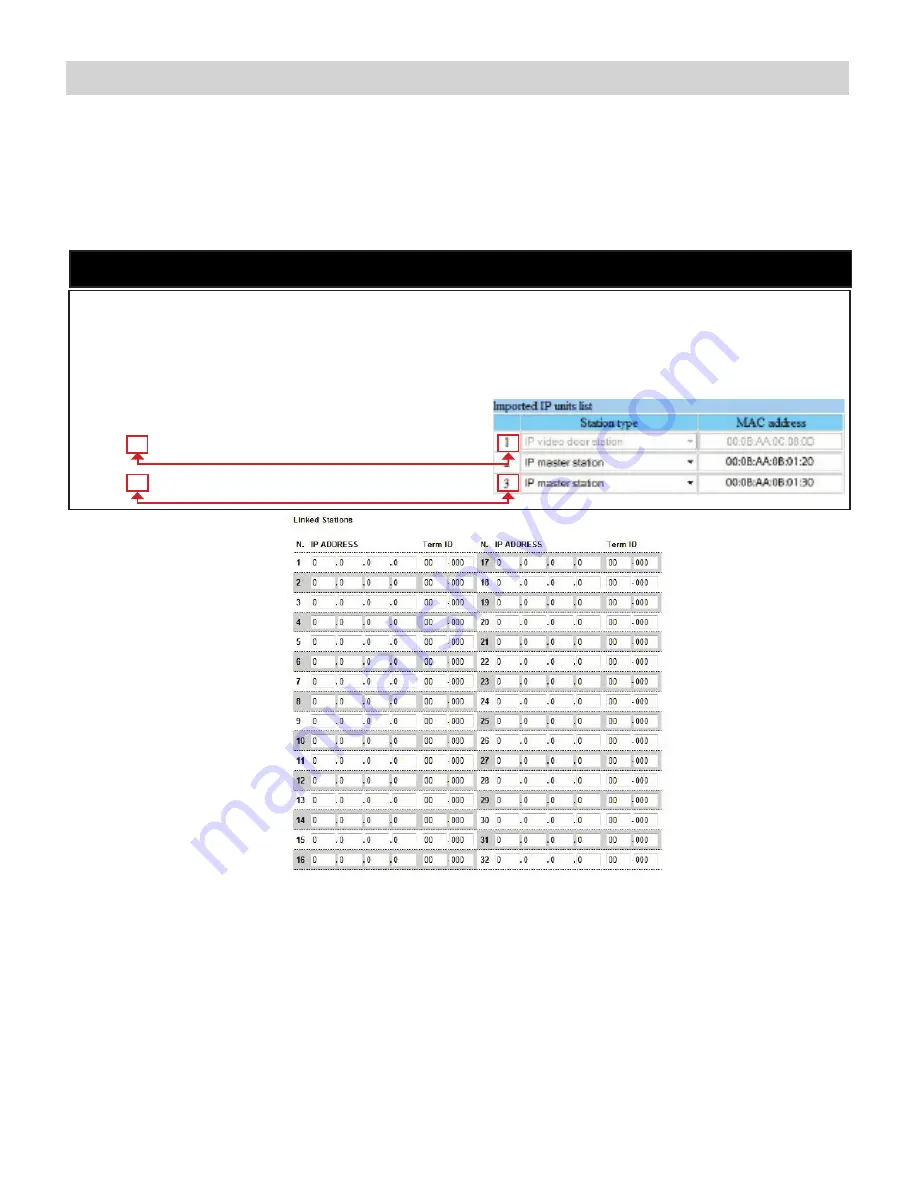
Linked Stations Table:

Enter the IP address and TermID for each IS-IP station in the IS configuration. This table is used as a reference for 

each TermID in the system. After inputting each IP address and TermID, click 

Apply Settings

 at the bottom of the 

page to save the settings to memory. Return to the Application Screen or reboot adaptor by clicking the 

Reboot

 button. 

Rebooting must occur to update adaptor settings.

A TermID identifies the location of an IS-IP station in the IS Series configuration. It also distinguishes between master 

stations and door stations. A master station TermID will be xx-001 and a door station TermID will be xx-101. “xx” 

represents the line in which the station resides under “IP Unit Registration” in the IS Host programming.

Example:  


01-101: Door station in address location 1.


03-001: Master station in address location 3.

Definition:


TermID

Relay Functionality:

Enter the TermID for the door station to be associated to the relay. 

Select the relay action from the drop down menu.


Relay Action options:

•  Door Release - Normally-Open

•  Door Release - Normally-Closed

• 

Active while Calling from source

• 

Active while in Communication with source

• 

Active during Calling and Communication

Relay will trigger when a configured master station pushes the door release button 

for the associated door.

Relay will trigger when the associated door station calls or communicates.

}

}

IS-IP Series:

 Relay Output Programming 

(cont.)

Summary of Contents for IS-IPRY

Page 1: ...IS IPRY Programming Manual For use with IX Series IS IP Series 1016 Input Output Network Adaptor...

Page 2: ...he IX Support Tool and for setting up the mobile device SIF ini File IX Series and IS IP Series Stations Only Create a SIF ini file in order for the IX Series and IS IP Series door stations and master...

Page 3: ...pdate to save the changes for the station then repeat the process for each station that will be associated with the IS IPRY F After completing steps C D and E for each station upload the changes Click...

Page 4: ...message will appear Continue to the website C Enter the administrator ID and password Default ID aiphone Default Password aiphone D Select Transmission setting under Uploading SIF setting data from th...

Page 5: ...d for access to the web browser interface AIPHONE Select the Aiphone system type the relay is to be used with The Aiphone system type that the relay is being integrated with will need to be selected C...

Page 6: ...y Closed Active while Calling from Source Active while Communicating Active during Calling and Communicating The IX Series allows for door release partitioning When the IS IPRY relay action is set for...

Page 7: ...number of the master stations to be called when the input is triggered When the target IP address is a door station a maximum of 20 master stations can be entered When the target IP address is a mast...

Page 8: ...a door station TermID will be xx 101 xx represents the line in which the station resides under IP Unit Registration in the IS Host programming Example 01 101 Door station in address location 1 03 001...

Page 9: ...ons Table see page 8 Check the Flag box beside each master station that will be allowed to trigger this relay for door release Once all master stations have been checked click Apply Settings at the bo...

Page 10: ...IX Mobile Server Functionality table Click on Apply Settings then click Reboot to restart the adaptor with the changes Refer to pages 12 15 for steps on adding a mobile device to the IX system using t...

Page 11: ...the other devices in the system 1 2 3 4 5 6 Click the button to save changes Click the button to save changes Note Station Information here to refer to later Number Name IP Address For Programmers In...

Page 12: ...e to C Program Files Support Tool System Data name of system Setting The IX Support Tool creates a configuration file for each device in the system and saves it to a folder within the Support Tool pro...

Page 13: ...e device Tap the Menu icon 6 6 7 Tap Setup Enter the Admin ID and Password and tap OK Default ID admin Default Password admin 7 8 8 A pop up will appear stating New configuration applied 9 To unlock t...

Page 14: ...iguration file saved from the IX Support Tool to this folder 1 2 3 4 5 1 2 3 4 5 Launch the application on the mobile device Tap the Menu icon then tap Settings 6 6 7 Tap Setup Enter the Admin ID and...

Page 15: ...PS 2420D R1 NO R3 NO Door Strike Bell Power Transformer use proper power for the strike mag lock or external signaling device being used PS 1215DIN PS 2420D R2 NO R4 NO R1 NO R3 NO R2 NO R4 NO I1 I2...

Reviews: