background image

Chapter 4: Troubleshooting
Over-Temperature Fault

66

Once you can see the case fans, apply AC power to the instrument and turn it on if it does not 
start up automatically. Visually check to see if any of the fans are not turning. If all the fans are 
not turning, it is probably a problem with the high side drive circuitry for the case fans. 

Figure 4-12

If any of these fans are turning then these fans are probably not the cause of your shutdown 
problem (you should still replace any fans that are not turning, however). If this is the case, the 
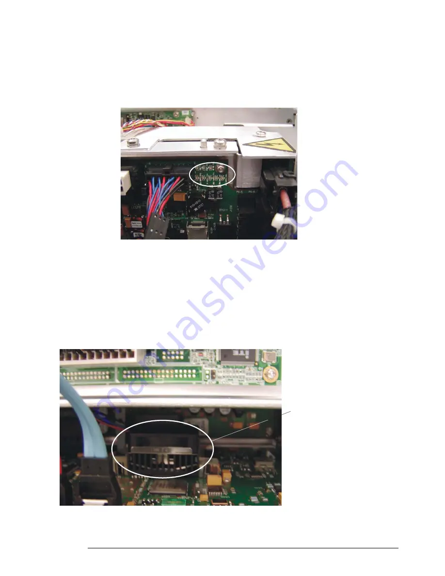
next step is to see if the FAN FAIL indicator LED is on in the upper right hand corner of the 
backplane assembly (refer to the circled area in Figure 4-12 above). If this LED is illuminated 
then that means the system thinks there is a fan failure. Since you have ruled out the case fans 
as the root of the problem, it may be that the trigger ICs fan has failed. To check this, first reset 
the logic by removing AC power for thirty seconds again. Then position yourself so you can see 
the trigger ICs fan on the back plane assembly. This fan is on the bottom of the backplane and, 
therefore, is somewhat hidden by the acquisition assemblies. You have to look down the 
backplane board to see it from above (see Figure 4-13 below).

Figure 4-13

This picture shows the location of the trigger ICs fan from the perspective of looking down the plane of the backplane assembly 
from above. 

Trigger ICs fan 
on backplane 
assembly

Summary of Contents for Infiniium 90000 A

Page 1: ...Service Guide Publication Number 54913 97022 March 2013 Agilent Technologies Inc 2007 2013 Infiniium 90000 A Series Oscilloscopes...

Page 2: ...implify complex measurement setups Horizontal controls set sweep speed and position Main sweep speeds from 5 ps div to 20 s div Zoom mode is from 1 ps div to main time base setting Intensified wavefor...

Page 3: ...n procedure Chapter 3 Testing Performance provides information about testing the oscilloscope to verify that it performs according to specifications Chapter 4 Troubleshooting provides information abou...

Page 4: ...4...

Page 5: ...ope 53 Primary Trouble Isolation 54 Power Supply Trouble Isolation 57 Under Voltage Fault 60 Over Temperature Fault 65 Over Voltage Fault 68 Display Trouble Isolation 71 To check the backlight inverte...

Page 6: ...108 To remove the backplane assembly from the acquisition assemblies 112 To set the calibration factors after replacing the acquisition board 113 To remove and replace the hard disk drive and the hard...

Page 7: ...nstruments covered by this service guide 8 Accessories supplied 10 Specifications and Characteristics 10 Environmental Conditions 11 Measurement Category 11 Oscilloscope Dimensions 12 General Informat...

Page 8: ...chnologies website at www agilent com to see whether a newer version of this manual is available The following 90000 A Series oscilloscopes are covered in this guide Table 1 1 Oscilloscopes Covered by...

Page 9: ...f the 90000 A Series oscilloscope This service guide covers both the standard and performance enhanced versions of the 90000 A Series scopes Any differences between the two versions are noted To tell...

Page 10: ...haracteristics refer to the data sheets at www agilent com find 90000 Specifications that are pertinent to each test are given in the Testing Performance chapter Specifications are valid after a 30 mi...

Page 11: ...asurements performed on circuits not directly connected to MAINS Examples are measurements on circuits not derived from MAINS and specially protected internal MAINS derived circuits In the latter case...

Page 12: ...6HQVL WLYLW OHDU LVSOD 4XLFN 0HDV RRP 5XQ 6WRS 6WRS 6LQJOH 6LQJOH 7RXFK X 2XW X 7ULJ OO QSXWV 9 0D 7 3XVK IRU 9HUQLHU HUQLHU HYHO QWHQVLW RUL RQWDO 5XQ RQWURO 7ULJJHU LVSOD 0HDVXUH 9HUWLFDO 6HOHFW 3RV...

Page 13: ...2 To run the self calibration 15 Calibration...

Page 14: ...14 Calibration This chapter provides self calibration procedures for the oscilloscope...

Page 15: ...down the Utilities menu and Select Calibration 3 Click the check box to clear the Cal Memory Protect condition You cannot run self calibration if this box is checked See Figure 2 1 Let the Oscilloscop...

Page 16: ...erence signal will not be required The remaining calibration procedure will continue b Disconnect everything from all inputs and Aux Out c Connect the calibration cable from Aux Out to channel 1 You m...

Page 17: ...ming Self Test and Calibration 19 Vertical Performance Verification 20 Offset Accuracy Test 21 DC Gain Accuracy Test 29 Analog Bandwidth Maximum Frequency Check 35 Time Scale Accuracy TSA 42 Performan...

Page 18: ...t Order The tests in this section may be performed in any order desired However it is recommended to conduct the tests in the order presented in this manual as this represents an incremental approach...

Page 19: ...n the Utilities menu and select Self Test b Select Scope Self Test from the Self Test list c Click on Start Self Test to start the self test procedure If any of the self tests fail ensure that the fai...

Page 20: ...20 Vertical Performance Verification This section contains the following vertical performance verification Offset Accuracy Test DC Gain Accuracy Test Analog Bandwidth Test...

Page 21: ...ion Let the oscilloscope warm up before testing The oscilloscope under test must be warmed up with the oscilloscope application running for at least 30 minutes prior to the start of any performance te...

Page 22: ...w is displayed enable averaging and set the of averages to 256 as shown below 3 Configure the scope to measure Average voltage on channel 1 as follows a Change the vertical sensitivity of channel 1 to...

Page 23: ...e Test Record 5 Change the vertical sensitivity of channel 1 to 10 mV div press the Clear Display key wait for the Avgs value top left corner of screen to return to 256 and then record the scope V avg...

Page 24: ...b Change the vertical sensitivity of channel 2 to 5 mV div c Click the V avg measurement icon on the left side of the screen d When the Enter Measurement Info window is displayed ensure that the Vavg...

Page 25: ...cope channel input to minimize ground potential differences and to ensure that the DMM measures the input voltage to the scope channel as accurately as possible Differences in ground potential can be...

Page 26: ...ed enable averaging and set the of averages to 256 c Change the vertical sensitivity of channel 1 to 5 mV div d Click the V avg measurement icon on the left side of the screen e When the Enter Measure...

Page 27: ...c Enter 400 0 mV in the Enter Offset dialog box 16 Set the Aux Out voltage VAux Out to 400 0 mV as follows a Pull down the Utilities menu and select Calibration b Change the Aux Output function to DC...

Page 28: ...in the Offset Gain Test section of the Performance Test Record 24 Calculate the offset gain error using the following expressions and record the value in the Offset Gain Test section of the Performanc...

Page 29: ...2 of full scale at full resolution channel scale Full scale is defined as 8 vertical divisions Magnification is used below 5 mV div Below 5 mV full scale is defined as 40 mV The major scale settings...

Page 30: ...to minimize ground potential differences and to ensure that the DMM measures the input voltage to the scope channel as accurately as possible Differences in ground potential can be a significant sourc...

Page 31: ...ollows a Pull down the Utilities menu and select Calibration b Change the Aux Output function to DC top left corner c Set the Level to 15 mV d Click on Close 4 Set the channel 1 vertical sensitivity v...

Page 32: ...for the Avgs value top left corner of screen to return to 256 and then record the scope s mean V avg reading in the DC Gain Test section of the Performance Test Record Notes For all scope readings in...

Page 33: ...Setup menu and select Acquisition When the Acquisition Setup window is displayed enable averaging and set the of averages to 256 b Change the vertical sensitivity of channel 2 to 5 mV div c Click the...

Page 34: ...n and record this value in the DC Gain Test section of the Performance Test Record For vertical sensitivities of less than 1 volt use the following equation For vertical sensitivity 1 V use the follow...

Page 35: ...0604A 6 0 GHz DSO DSA90404A 4 0 GHz DSO DSA90254A 2 5 GHz Description Critical Specifications Recommended Model Part Numbers Microwave CW Generator Maximum Frequency 14 GHz Power range 20 dBm to 16 dB...

Page 36: ...nsure Channel 1 is displayed and all other channels are turned off b Set the vertical sensitivity of channel 1 to 5 mV div Notes Connect output 1 of the 11667B splitter to the scope Channel n input di...

Page 37: ...cles of a 50 MHz waveform d Pull down the Setup menu select Acquisition and then set up the acquisition parameters as follows Memory Depth Automatic Sampling rate Maximum 40 GSa s Sin x x Interpolatio...

Page 38: ...mended amplitude then set the generator to the highest value that does not produce a vertically clipped signal on the scope Table 3 1 Nominal Generator Amplitude Settings 8 Measure the input power to...

Page 39: ...0 Calculate the reference gain as follows Record this value in the Calculated Gain 50 MHz column in the Analog Bandwidth Maximum Frequency Check section of the Performance Test Record Notes For all sc...

Page 40: ...og Bandwidth Maximum Frequency Check section of the Performance Test Record Vout Max Freq 15 Calculate the gain at the maximum frequency using the expression For example if Vout Max Frequency 13 825 m...

Page 41: ...Right click on the V rms measurement at the bottom of the screen When the RMS voltage measurement setup window is displayed change the source from Channel 1 to Channel 2 22 Repeat steps 7 to 20 to com...

Page 42: ...te that TSA is specified with respect to an absolute standard and therefore its measurement results mustbe comparedagainsttestlimits thataccountfortheuncertaintiesinits measurement results The total m...

Page 43: ...e to 20 ms div 7 Set the measurement thresholds for all waveforms to a fixed voltage level of 0 V and 20 mV hysteresis 8 Enable a frequency measurement on channel 1 9 On the oscilloscope press Stop 10...

Page 44: ...rformance Time Scale Accuracy TSA 44 measurement result should exceed the specified accuracy by at least 0 1 ppm in order to guarantee compliance to the specification 16 Record the results in the Perf...

Page 45: ...______ Recommended Test Interval 1 Year 2000 hours Date___________________ Recommended next test date ___________________ Ambient temperature ___________________ Vertical Sensitivity Test Limits Chann...

Page 46: ...div 2 4 V 2 500 mV div 2 4 V 2 1 V div 2 4 V 2 Channel 2 5 mV div 400 mV 2 10 mV div 400 mV 2 20 mV div 400 mV 2 50 mV div 900 mV 2 100 mV div 1 6 V 2 200 mV div 2 4 V 2 500 mV div 2 4 V 2 1 V div 2 4...

Page 47: ...500 mV div 1 5 V 2 1 V div 2 4 V 2 Channel 2 5 mV div 15 mV 2 10 mV div 30 mV 2 20 mV div 60 mV 2 50 mV div 150 mV 2 100 mV div 300 mV 2 200 mV div 600 mV 2 500 mV div 1 5 V 2 1 V div 2 4 V 2 Channel...

Page 48: ...nt Vin 50 MHz Vout 50 MHz Calculated Gain 50 MHz Test Limit greater than 3 dB Vin Max Freq Vout Max Freq Calculated Gain Max Freq Test Limit greater than 3 dB Channel 1 5 mV div 10 mV div 20 mV div 50...

Page 49: ...ecord 49 Test Limits Results Time Scale Accuracy Limit Limit is based on years since oscilloscope s last calibration Calculated TSA Spec Measuredtime scale error Pass Fail TSA 0 4 0 5 Years Since Cali...

Page 50: ...Chapter 3 Testing Performance Performance Test Record 50...

Page 51: ...oltages 73 To check the display board video signals 74 Front Panel Display Trouble Isolation 75 Front Panel Trouble Isolation 77 Motherboard Verification 78 To setup the BIOS 79 Acquisition Backplane...

Page 52: ...ack in place before turning the oscilloscope on If the procedure requires you to have the cover off be careful not to contact these fan blades with any part of your body Tools Required You will need b...

Page 53: ...ty assembly use the disassembly and assembly procedures in Replacing Assemblies beginning on page 89 to replace the assembly The primary procedural toolin this section is the Primary Trouble Isolation...

Page 54: ...y two seconds for the scope to lose power go to the Under voltage Fault section in this chapter 2 If it takes four seconds or more for the scope to lose power go to the Over temperature Fault section...

Page 55: ...both directions until you have turned all knobs When you turn a knob in one direction half the rotation arrow under the corresponding knob symbol should turn green When you then turn the knob in the o...

Page 56: ...look at the details to see the channel associated with the fail If it is not channel 1 then replace the acquisition board associated with that channel channels 1 and 2 lower acquisition board channel...

Page 57: ...rform the maintenance Read the safety summary at the back of this book before proceeding Failure to observe safety precautions may result in electric shock WARNING SHOCK HAZARD Once the bulk 12V power...

Page 58: ...Chapter 4 Troubleshooting Power Supply Trouble Isolation 58 Figure 4 4...

Page 59: ...aults under voltage faults a defective power supply is included in this section over temperature faults and over voltage faults The following sections will describe each of these faults in detail so y...

Page 60: ...have determined that it takes approximately two seconds for the oscilloscope to lose power the next step is to remove the handle the outer oscilloscope cover and the inner top cover This will expose...

Page 61: ...minated when AC power is applied to the instrument the bulk 12V supply might need to be replaced Be sure to verify the operation of the AC OK and DC OK signals first The AC OK signal indicates that th...

Page 62: ...there is a short on this board you would measure something very near zero ohms If there is a short disconnect the power cable to the front panel see Figure 4 6 and redo the resistance measurement If...

Page 63: ...9 This figure shows how to measure the acquisition assembly resistance between 12V and ground on the back side of the board on the right end of the power connector If no shorts are found on the bulk 1...

Page 64: ...cope still will not power on after you have followed the required steps in this Power Supply Trouble Isolation section and assuming you have looked through the other two sections included in this Powe...

Page 65: ...embly that cools the trigger ICs In order for the instrument to shut down because of a cooling system fault one of the following condition must exist The circuitry that generates the reference potenti...

Page 66: ...rner of the backplane assembly refer to the circled area in Figure 4 12 above If this LED is illuminated then that means the system thinks there is a fan failure Since you have ruled out the case fans...

Page 67: ...ot to touch the fan blades with your fingers The unit will shut down Reset the logic by removing AC power for thirty seconds and make the case fans so they all cannot rotate for example either by two...

Page 68: ...that the oscilloscope loses power almost immediately the next step is to remove the handle the outer oscilloscope cover and the inner top cover This will expose the mother board cavity and the top ed...

Page 69: ...ing picture Figure 4 16 shows the fan opening with the fan removed This is done to shows where these LEDs are located on the acquisition assemblies and is not required in your actual diagnosis You wil...

Page 70: ...see any of these over voltage LEDs illuminated that acquisition assembly needs to be replaced If the oscilloscope still will not power on after you have followed the required steps in this Power Suppl...

Page 71: ...Chapter 4 Troubleshooting Display Trouble Isolation 71 Display Trouble Isolation...

Page 72: ...er and check power up sequence Power up displayed on ext monitor Replace Display Board Go to Primary Trouble Isolation Go to Power Supply Trouble Isolation Go to To check the backlight Inverter voltag...

Page 73: ...n the two wires when the backlight is illuminated The voltage is approximately 1 kV before the backlight tube is illuminated A red LED on the backlight inverter board illuminates when the output volta...

Page 74: ...are not present suspect the display card If the signals are present and the backlights are on suspect the flat panel display as the problem Note that CLK A0 A1 A2 and A3 are Low Voltage Differential...

Page 75: ...and LCD No Does front panel display work Try a golden display card to verify failure Does display work with golden card Replace LCD Replace display card Replace motherboard Check inverter board contr...

Page 76: ...CAN RESULT Once the cover is removed the fan blades are exposed both inside and outside the chassis Disconnect the power cable before working around the fans Use extreme caution in working with the o...

Page 77: ...er 4 Troubleshooting Front Panel Trouble Isolation 77 Front Panel Trouble Isolation Front Panel TroubleIsolation Followthekeyboard troubleshootingguidefor just thepower button Goto PrimaryTrouble Isol...

Page 78: ...trument Then unplug the front panel power cable see Figure 4 6 the two large power cables that go to the motherboard power harness J1201 and J1202 see Figure 4 8 and the red and blue SATA cables J900...

Page 79: ...ess Delete when the following prompt appears on the bottom of the screen Press TAB to Show POST screen DEL to enter SETUP F12 to select boot device If the prompt does not appear or the oscilloscope do...

Page 80: ...he linearity of each channel s front end DAC If the test finds a problem it will report a failure for the DAC on the associated channel Board Level Repair Re solder or replace the DAC that is failing...

Page 81: ...rs cannot be corrected the Hedwig IC with the associate errors must be replaced Hedwig Register Test This test verifies that all of the Hedwig memory controller ASIC registers can be correctly written...

Page 82: ...hat is outside of the expected operating range a failure will be reported for the IC associated with that temperature sensor Board Level Repair This test should never fail since the oscilloscope will...

Page 83: ...toProbe Board Trouble Isolation AutoProbe Board Trouble Isolation Inspect the cable between the AutoProbe assembly and the power board Cable OK Replace bad cable No Yes Turn unit on Does unit turn ON...

Page 84: ...ssembly CAUTION CONTAMINATION CAN CAUSE INTERMITTENT OPERATION Be careful not to contaminate the key side of the PC board or the keypads Dust and fingerprints on these parts may cause intermittent key...

Page 85: ...ecting the ON OFF board to the motherboard If any of the other LEDs are not working on the front panel the first step is to trouble shoot the acquisition assemblies to make sure they are working If th...

Page 86: ...om the Help Menu A dialog box appears showing the current version number for the scope software and on line information system software This information may be useful when contacting Agilent Technolog...

Page 87: ...board Usethetableandfiguretotheright to check the power output at the connectors The 12 V and 12 V supplies come from ripple regulator on the power board and the 3 V and 3 V supplies are developed in...

Page 88: ...Chapter 4 Troubleshooting To check probe power outputs 88...

Page 89: ...d 103 To remove and replace the touch screen the front deck and the controller assembly 104 To remove and replace the acquisition boards backplane assembly 108 To set the calibration factors after rep...

Page 90: ...uired for these procedures Torx drivers T10 T20 Socket wrench 9 16 inch Torque wrench 3 5 mm 8 in lbs Medium size 3 16 in flat blade screwdriver CAUTION REMOVE POWER BEFORE REMOVING OR REPLACING ASSEM...

Page 91: ...t to the oscilloscope Name and address of owner Oscilloscope model numbers Oscilloscope serial numbers Description of the service required or failure indications 2 Remove all accessories from the osci...

Page 92: ...es and BNC input cables from the front panel 3 Disconnect any other cables such as mouse keyboard printer USB or LAN cables 4 Remove the accessory pouch from the top of the oscilloscope if it is attac...

Page 93: ...over top plate and bottom plate 93 Figure 5 3 Figure 5 4 8 Carefully slide the cover towards the rear of the instrument and off the chassis as shown in Figure 5 5 Figure 5 5 9 Once the cover is remove...

Page 94: ...e top plate and lift off as shown in Figure 5 7 Figure 5 6 Figure 5 7 10 To remove the bottom plate flip the oscilloscope upside down and remove the three Torx T20 screws from the bottom panel as show...

Page 95: ...lace the cover top plate and bottom plate 95 Figure 5 8 Figure 5 9 Figure 5 10 11 To replace the cover top plate and bottom plate reverse the above procedure Please note that all sheet metal holes tha...

Page 96: ...o remove and replace the cover top plate and bottom plate 96 marked by lines on four sides of the hole as shown in Figure 5 11 Figure 5 11 CAUTION PROPERLY TIGHTEN HANDLE AND SCREWS Tighten the side h...

Page 97: ...plate 2 Disconnect front panel cables 3 Grasp and pull on all 13 knobs located on the front panel to remove them Figure 5 12 Figure 5 12 4 Use a screw driver to disengage locking tabs located along th...

Page 98: ...ng Assemblies To remove and replace the front panel bezel and front panel circuit assembly 98 Figure 5 13 Figure 5 14 5 Remove two Torx T10 screws from the front panel printed circuit assembly as show...

Page 99: ...scussed in step 1 You can see the top left side tab by looking through the top cavity while you can see the bottom left tab by turning the oscilloscope on its side and looking through the bottom cavit...

Page 100: ...zel and front panel circuit assembly 100 Figure 5 16 Figure 5 17 This figure shows the top left hand side tab for the control panel faceplate The view is through the top cavity standing at the rear of...

Page 101: ...sis itisbesttosnapthefaceplateandtheassemblytogether first before trying to attach them back to the chassis via these tabs Once they are attached together snap down the right hand side tabs first and...

Page 102: ...Chapter 5 Replacing Assemblies To remove and replace the on off board 102 Figure 5 20 4 To replace the on off board reverse the above procedure...

Page 103: ...of the oscilloscope near the flat panel display operates at high voltages from 300 1 kVACrms DO NOT handle this assembly while it is in operation 1 Disconnect the power cable and remove the cover and...

Page 104: ...e and remove the cover top plate and bottom plate 2 Remove the front panel bezel and front panel circuit assembly from the chassis 3 Remove the two Torx T20 screw attaching the touch screen to the fro...

Page 105: ...deck two on the right hand side and two on the left hand side See Figure 5 24 Figure 5 24 7 Turn the oscilloscope upside down or on its side and look through the bottom cavity to see the SMA connecto...

Page 106: ...to the front deck This gives you some room to feed cables through the correct holes and attach them to the correct boards When reattaching the SMA cables use an 8 lb torque wrench as shown in Figure...

Page 107: ...ese cables on page 117 3 Remove the Torx T10 screws attaching the motherboard to the frame Figure 5 28 The motherboard shown below is the one in the standard 90000A models If you have a performance en...

Page 108: ...his printing Your unit may look different 1 Disconnect the power cable and remove the cover top plate and bottom plate 2 Remove the motherboard and bulk 12V power supply 3 Turn the oscilloscope on its...

Page 109: ...backplane assembly 109 Figure 5 32 6 Remove the Torx T20 screws from the top of the backplane assembly Figure 5 33 Figure 5 33 7 Flip the instrument so it is upside down or on its side 8 Remove the To...

Page 110: ...wo Torx T20 screws from the underside of the backplane assembly Figure 5 35 Figure 5 35 10 If unit is not upside down if you chose to just lay it on its side go ahead and flip it upside down right now...

Page 111: ...Chapter 5 Replacing Assemblies To remove and replace the acquisition boards backplane assembly 111 Figure 5 36...

Page 112: ...tion 2 Remove the four Torx T20 screws two per acquisition assembly on the side of the backplane assembly Figure 5 37 Figure 5 37 3 Gently pry on the sheet metal portions to separate the backplane ass...

Page 113: ...erformance 2 Performance calibration After the warm up period calibrate the oscilloscope a Connect the RS 232 cable to the Digital Multimeter RS 232 port and to the RS 232 port on the oscilloscope b S...

Page 114: ...fter replacing the acquisition board 114 c Pull down the Utilities menu and select Calibration d Uncheck the Cal Memory Protect box to allow calibration e Click on Start to start the calibration proce...

Page 115: ...at the time of this printing Your unit may look different 1 Disconnect the power cable and remove the cover and top plate 2 Disconnect the two cables connected to the hard drive 3 Remove the two latc...

Page 116: ...r 5 Replacing Assemblies To remove and replace the hard disk drive and the hard drive control board 116 Figure 5 41 6 To replace the hard disk drive and hard drive control board reverse the above proc...

Page 117: ...tures show close ups of each cable Figure 5 51 shows the performance enhanced 90000A motherboard so you know where to reconnect the cables The cables are the same on the performance enhanced models bu...

Page 118: ...semblies Cable removal for replacing the motherboard 118 Figure 5 43 Figure 5 44 Figure 5 45 S A T Aca blebetwe en m otherboarda nd ha rddrive F ront pa ne l U S B ca ble S A T Aca bles between ba ckp...

Page 119: ...emblies Cable removal for replacing the motherboard 119 Figure 5 46 Figure 5 47 Figure 5 48 D ispla yca ble between m otherboarda nd front pa nel P ower harness between ba ckplanea nd m otherboard P o...

Page 120: ...Chapter 5 Replacing Assemblies Cable removal for replacing the motherboard 120 Figure 5 49 Figure 5 50 P owerharness between backplaneand m otherboard O n O ff ca ble...

Page 121: ...Chapter 5 Replacing Assemblies Cable removal for replacing the motherboard 121 Figure 5 51 Motherboard and cables in performance enhanced 90000 A Series models...

Page 122: ...it could have a dangerous charge on some capacitors This charge could remain for many days after removing power from the supply WARNING SHOCK HAZARD When the power supply is removed two AC leads are e...

Page 123: ...ative of the oscilloscope at the time of this printing Your unit may look different 1 Disconnect the power cable and remove the cover and top plate 2 Disconnect the fan harness cables 3 Clip off the e...

Page 124: ...f this printing Your unit may look different 1 Disconnect the power cable and remove the cover and top plate 2 Unplug the power cable from the 12V power supply refer to Figure 5 52 for the location of...

Page 125: ...only one will be shown here When necessary refer to other removal procedures The graphics in this chapter are representative of the oscilloscope at the time of this printing Your unit may look differ...

Page 126: ...Chapter 5 Replacing Assemblies To remove and replace the USB or GPIB port 126...

Page 127: ...6 Ordering Replaceable Parts 128 Listed Parts 128 Unlisted Parts 128 Direct Mail Order System 128 Exchange Assemblies 128 Exploded Views 129 Replaceable Parts List 133 Replaceable Parts...

Page 128: ...Mail Order System Within the USA Agilent Technologies can supply parts through a direct mail order system There are several advantages to this system Direct ordering and shipping from the Agilent Tech...

Page 129: ...Chapter 6 Replaceable Parts Exploded Views 129 Exploded Views Front Frame and Front Panel...

Page 130: ...Chapter 6 Replaceable Parts Exploded Views 130 Fan and Acquisition Assembly...

Page 131: ...Chapter 6 Replaceable Parts Exploded Views 131 Power Supply and PC Motherboard...

Page 132: ...Chapter 6 Replaceable Parts Exploded Views 132 Sleeve and Accessory Pouch...

Page 133: ...inted Circuit Assembly 8 GHz and above Exchange replaces 54913 69501 A12 54906 66501 2 Acquisition Printed Circuit Assembly 6 GHz and below replaced by 54906 66511 A12 54906 69501 2 Acquisition Printe...

Page 134: ...ce enhanced models MP1 54913 94335 1 Label DSO 90404A performance enhanced models MP1 54913 94336 1 Label DSO 90254A performance enhanced models MP1 54913 94346 1 Label DSA 90254A performance enhanced...

Page 135: ...an not shown W6 54913 61604 1 Cable ON OFF not shown W7 54913 61608 1 Cable Display not shown W8 54913 61601 4 Cable Input not shown 54913 61607 1 Cable USB Touch standard models 54913 61617 1 Cable U...

Page 136: ...Chapter 6 Replaceable Parts Replaceable Parts List 136...

Page 137: ...7 Block Level Theory 139 Power Supply Assembly 141 Monitor Assembly 141 Acquisition System 141 Front Panel 142 Motherboard 144 On Off Board 144 Theory of Operation...

Page 138: ...Chapter 7 Theory of Operation 138 Figure 7 1 Oscilloscope Block Diagram...

Page 139: ...utoProbe interface for probe power and probe control A connection for probe compensation The rear panel provides several connections The line power input A GPIB connector for connection to an oscillos...

Page 140: ...Chapter 7 Theory of Operation Block Level Theory 140 Figure 7 2 AcquisitionBoards BackplaneBoard...

Page 141: ...d is essentially a device on the PCI Express bus connected by two SATA cables to the motherboard The backplane board recieves 12V power through a distribution board from the supply and all voltage are...

Page 142: ...he scope PC motherboard through a high speed USB 2 0 interface The on board USB hub serves the PIC microcontroller the touch screen controller board and up to three front panel USB connectors for a cu...

Page 143: ...yboard block diagram Disk Drive The hard disk drive is a high capacity shock resistant unit It is used to store the oscilloscope s operating system and certain system configuration data The drive can...

Page 144: ...ovide the probe compensation output Power indicator LEDs backlight the on off pushbutton and are driven by the motherboard The probe compensation lugs connect to the calibrator output on the backplane...

Page 145: ...FPGA Hedwig Memory Controller Hedwig Memory Controller Acq FPGA Acq FPGA Hedwig Memory Controller Hedwig Memory Controller Config PROM Philips PX 1011A Misc I Cs SATA Conn Backplane Board Acq board A...

Page 146: ...146 Figure 7 6 Acquisition board block diagram...

Page 147: ...y that the ground protection is impaired you must make the instrument inoperative and secure it against any unintended opera tion Service instructions are for trained service personnel To avoid danger...

Page 148: ...Warranty The material contained in this document is provided as is and is subject to being changed without notice in future editions Further to the maximum extent permitted by applica ble law Agilent...

Reviews: