


Chapter 4: Troubleshooting
Under-Voltage Fault
60
Under-Voltage Fault
If the oscilloscope turns off without you pressing the front panel power button then the first
step is to unplug the oscilloscope so the +5V standby supply can fully discharge (this takes
around 30 seconds). Then plug the oscilloscope back in. Press the front panel power button
and count how many seconds it takes for the oscilloscope to lose power again (once the
oscilloscope loses power, keep it plugged in). If it takes around two seconds then you either
have an under-voltage fault on the backplane assembly or one of the two acquisition assemblies
or you have a defective bulk 12V power supply. This section will walk you through how to
determine which of these is the actual problem and how to fix it.
Once you have determined that it takes approximately two seconds for the oscilloscope to lose
power, the next step is to remove the handle, the outer oscilloscope cover, and the inner top
cover. This will expose the mother board cavity and the top edges of the backplane assembly.
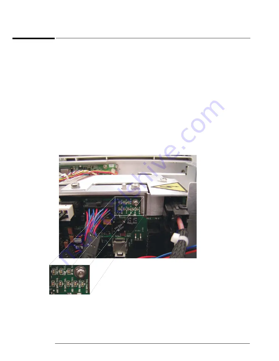
There are a series of six under-voltage indicator LEDs located in the upper right corner of the
backplane assembly (see Figure 4-5 below). The other LEDs in this section of the backplane
assembly indicate over-temperature or fan problems and will be discussed in the Over-
temperature Fault section.
Figure 4-5
The white box and subsequent enlargement highlight the section on the backplane assembly where the under-voltage fault
LEDs are located.
Each one of these six under-voltage fault LEDs are labelled. If only the ACQ1 SUPPLY FAIL
LED is illuminated, replace the channels 3 and 4 acquisition assembly (UPPER ACQ). If only
the ACQ2 SUPPLY FAIL LED is illuminated, replace the channels 1 and 2 acquisition assembly
Summary of Contents for Infiniium 90000 A
Page 4: ...4...
Page 13: ...2 To run the self calibration 15 Calibration...
Page 14: ...14 Calibration This chapter provides self calibration procedures for the oscilloscope...
Page 50: ...Chapter 3 Testing Performance Performance Test Record 50...
Page 58: ...Chapter 4 Troubleshooting Power Supply Trouble Isolation 58 Figure 4 4...
Page 71: ...Chapter 4 Troubleshooting Display Trouble Isolation 71 Display Trouble Isolation...
Page 88: ...Chapter 4 Troubleshooting To check probe power outputs 88...
Page 126: ...Chapter 5 Replacing Assemblies To remove and replace the USB or GPIB port 126...
Page 129: ...Chapter 6 Replaceable Parts Exploded Views 129 Exploded Views Front Frame and Front Panel...
Page 130: ...Chapter 6 Replaceable Parts Exploded Views 130 Fan and Acquisition Assembly...
Page 131: ...Chapter 6 Replaceable Parts Exploded Views 131 Power Supply and PC Motherboard...
Page 132: ...Chapter 6 Replaceable Parts Exploded Views 132 Sleeve and Accessory Pouch...
Page 136: ...Chapter 6 Replaceable Parts Replaceable Parts List 136...
Page 138: ...Chapter 7 Theory of Operation 138 Figure 7 1 Oscilloscope Block Diagram...
Page 146: ...146 Figure 7 6 Acquisition board block diagram...


