


Chapter 4: Troubleshooting
Over-Voltage Fault
68
Over-Voltage Fault
If the oscilloscope turns off without you pressing the front panel power button, the first step is
to unplug the oscilloscope so the +5V standby supply can fully discharge (this takes around 30
seconds). Then plug the oscilloscope back in. Press the front panel power button and count
how many seconds it takes for the oscilloscope to lose power again (once the oscilloscope loses
power, keep it plugged in). If the oscilloscope shuts down almost immediately, it is probably
an over-voltage fault.
Once you have determined that the oscilloscope loses power almost immediately, the next step
is to remove the handle, the outer oscilloscope cover, and the inner top cover. This will expose
the mother board cavity and the top edges of the backplane assembly.
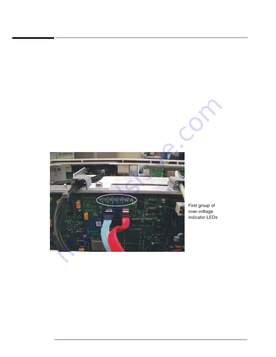
There are three groups of LEDs that indicate over-voltage faults. One group is located near the
center of the top edge of the backplane assembly just above the blue and red SATA cables
(Figure 4-14).
Figure 4-14
If any of these LEDs are on, the backplane assembly must be replaced.
The other two groups of LEDs that indicate over-voltage faults are located along the edges of
the two acquisition assemblies and are visible through the bottom fan opening located on the
left side of the oscilloscope (nearest the rear panel - see Figure 4-15 and Figure 4-16).
Summary of Contents for Infiniium 90000 A
Page 4: ...4...
Page 13: ...2 To run the self calibration 15 Calibration...
Page 14: ...14 Calibration This chapter provides self calibration procedures for the oscilloscope...
Page 50: ...Chapter 3 Testing Performance Performance Test Record 50...
Page 58: ...Chapter 4 Troubleshooting Power Supply Trouble Isolation 58 Figure 4 4...
Page 71: ...Chapter 4 Troubleshooting Display Trouble Isolation 71 Display Trouble Isolation...
Page 88: ...Chapter 4 Troubleshooting To check probe power outputs 88...
Page 126: ...Chapter 5 Replacing Assemblies To remove and replace the USB or GPIB port 126...
Page 129: ...Chapter 6 Replaceable Parts Exploded Views 129 Exploded Views Front Frame and Front Panel...
Page 130: ...Chapter 6 Replaceable Parts Exploded Views 130 Fan and Acquisition Assembly...
Page 131: ...Chapter 6 Replaceable Parts Exploded Views 131 Power Supply and PC Motherboard...
Page 132: ...Chapter 6 Replaceable Parts Exploded Views 132 Sleeve and Accessory Pouch...
Page 136: ...Chapter 6 Replaceable Parts Replaceable Parts List 136...
Page 138: ...Chapter 7 Theory of Operation 138 Figure 7 1 Oscilloscope Block Diagram...
Page 146: ...146 Figure 7 6 Acquisition board block diagram...


