


Chapter 4: Troubleshooting
Primary Trouble Isolation
55
D
Check the front panel response by running the Keyboard and LED self tests.
Use this procedure to verify correct keyboard operation.
1
Select Self Test from the Utilities menu.
2
Select Keyboard Test from the Self Test drop down list box, then click Start.
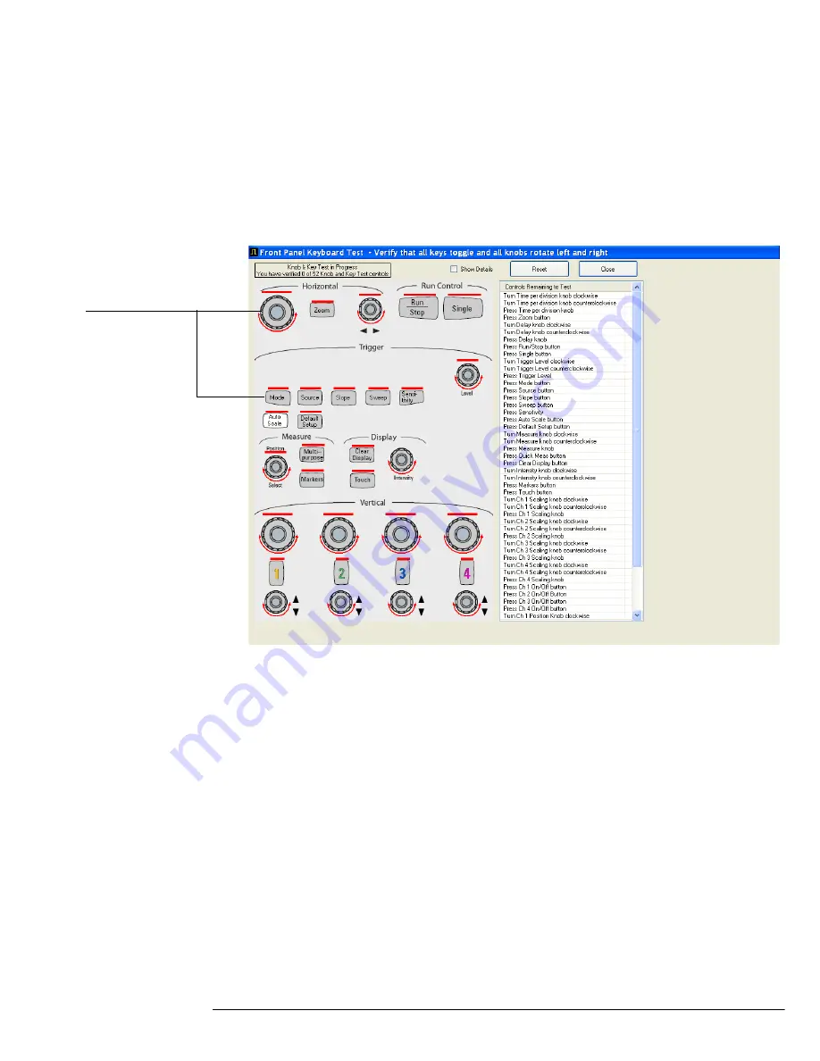
A new window appears with a symbolic representation of the keyboard. See Figure 4-2.
Figure 4-2
Knob and Key Self Test Screen
3
Press each key on the keyboard until you have pressed all keys.
When you press a key or turn a knob, the bar above the corresponding key/knob
symbol on the display should change from red to green.
4
Turn each knob in both directions until you have turned all knobs.
When you turn a knob in one direction, half the rotation arrow under the
corresponding knob symbol should turn green. When you then turn the knob in the
other direction, the entire rotation arrow under the knob symbol should turn green.
5
When you are finished, click Close.
6
If any of the knobs or keys do not work, go to To check the keyboard; Trouble Isolation
Procedure 84.
Use the following procedure to test the front-panel LED (light-emitting diode) indicators.
1
Select Self Test from the Utilities menu.
2
Select LED Test from the Self Test drop-down list box, then click Start Test.
The LED test screen appears, which shows a symbolic representation of all front panel LED
indicators. See Figure 4-3.
When you press a key
or turn a knob in both
directions, the
corresponding
symbol on this screen
turns green.
Summary of Contents for Infiniium 90000 A
Page 4: ...4...
Page 13: ...2 To run the self calibration 15 Calibration...
Page 14: ...14 Calibration This chapter provides self calibration procedures for the oscilloscope...
Page 50: ...Chapter 3 Testing Performance Performance Test Record 50...
Page 58: ...Chapter 4 Troubleshooting Power Supply Trouble Isolation 58 Figure 4 4...
Page 71: ...Chapter 4 Troubleshooting Display Trouble Isolation 71 Display Trouble Isolation...
Page 88: ...Chapter 4 Troubleshooting To check probe power outputs 88...
Page 126: ...Chapter 5 Replacing Assemblies To remove and replace the USB or GPIB port 126...
Page 129: ...Chapter 6 Replaceable Parts Exploded Views 129 Exploded Views Front Frame and Front Panel...
Page 130: ...Chapter 6 Replaceable Parts Exploded Views 130 Fan and Acquisition Assembly...
Page 131: ...Chapter 6 Replaceable Parts Exploded Views 131 Power Supply and PC Motherboard...
Page 132: ...Chapter 6 Replaceable Parts Exploded Views 132 Sleeve and Accessory Pouch...
Page 136: ...Chapter 6 Replaceable Parts Replaceable Parts List 136...
Page 138: ...Chapter 7 Theory of Operation 138 Figure 7 1 Oscilloscope Block Diagram...
Page 146: ...146 Figure 7 6 Acquisition board block diagram...


