


24
N9912A FieldFox User’s Guide
Press
Next Page
and
Previous Page
to view all settings. If these softkeys are
NOT available, then all available settings fit on one page.
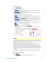
To change a setting:
o
Use the
▲|▼
arrows to highlight a setting.
o
Then press
Edit
. The current setting changes to
yellow.
o
Some settings require you to press a softkey to change the value. Otherwise,
use the numeric keypad,
▲|▼
arrows, or rotary knob to change the value.
o
When finished changing a value, press
Done Edit
.
Press
Dock Window
to relocate the Settings table to a position relative to the
trace window. The Dock Window setting persists through a Preset. Choose
from the following:
o
Full (Default setting)
Only the Settings table is shown on the screen. The
trace window is temporarily not shown.
o
Left
The Settings table is shown to the left of the trace window.
o
Bottom
The Settings table is shown below the trace window.
When finished changing ALL settings, press
Done
to save your settings.
Frequency Range
Set the range of frequencies over which you would like to make CAT Mode
measurements.
When the frequency range is changed after a calibration is performed, the cal
becomes interpolated. Learn more on page 65.
How to set Frequency Range
Press
Freq/Dist
.
Then choose from the following:
o
Start
and
Stop
frequencies - beginning and end of the sweep.
o
Center
and
Span
frequencies – the center frequency and span of
frequencies (half on either side of center).
Follow each setting by entering a value using the numeric keypad,
▲|▼
arrows, or the rotary knob.
o
After using the keypad, select a multiplier key. Learn about multiplier
abbreviations on page 19.
o
After using the
▲|▼
arrows or the rotary knob, press
Enter
. The amount of
frequency increment is based on the current span and can NOT be changed
in CAT Mode.
Scale Settings
Adjust the Y-axis scale to see the relevant portions of the data trace. The Y-axis is
divided into 10 graticules.
This setting can be changed at any time without affecting calibration accuracy.
Summary of Contents for FieldFox N9912A
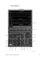
Page 15: ...Preparing for Initial Use of Your New FieldFox 15 Take the FieldFox Tour Front Panel ...
Page 194: ...194 N9912A FieldFox User s Guide Batteries Safe Handling and Disposal ...
Page 195: ...Safety Considerations 195 Inspired Energy Battery ...
Page 196: ...196 N9912A FieldFox User s Guide ...
Page 197: ...Safety Considerations 197 ...
Page 198: ...198 N9912A FieldFox User s Guide ...


