


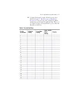


Test 4. Optical Input Return Loss
6
-
9
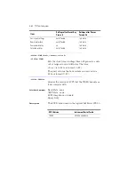
Compare this measurement with the specification listed
in
Chapter 7, “Specifications and Regulatory
.
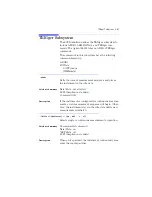
Procedure
Option 022 instruments (angled contacting con-
nectors)
1
Turn off the output of the source module.
2
Connect a single-mode patchcord between the optical
output of the source module and the
INPUT SOURCE
connector of the return loss module
.
3
Set the wavelength on the return loss module to
1550 nm, and select an average time of 1 second.
4
Locate an HMS-10/HP/HRL to FC/APC (angled FC)
patchcord. Connect the HMS-10/HP/HRL end of the
patchcord to the
OUTPUT
connector of the return loss
module. Terminate the FC/APC end of the cable.
5
Zero the return loss module.
6
Turn on the source module.
7
Remove the termination from the cable, and connect the
FC/APC end of an FC/APC to FC/PC cable to the free
end of this cable. Leave the free end of the cable
uncovered.
8
The return loss module measures the reflection
reference (14.6 dB return loss of the FC/PC connector of
the patchcord in air).
9
Disconnect the FC/APC to FC/PC cable.
10
Make a low-reflection termination in the HMS-10/HP/
HRL to FC/APC patchcord. Do this by wrapping the
cable around a 5 mm diameter mandrel six times.
11
The return loss module measures the termination
parameter.
12
Connect the HMS-10/HP/HRL to FC/APC patchcord to
the front-panel
OPTICAL INPUT
connector of the
Agilent 86121A.
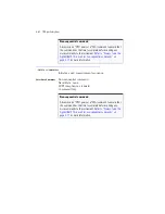
13
The lightwave multimeter measures the return loss.
Compare this measurement with the specification listed
in
Chapter 7, “Specifications and Regulatory
.
Summary of Contents for 86121A
Page 2: ...User s Guide Agilent 86121A WDM Channel Analyzer ...
Page 7: ......
Page 10: ...Chapter 1 Getting Started ...
Page 21: ......
Page 24: ...Agilent 86121A Front and Rear Panels 2 3 Agilent 86121A Front and Rear Panels ...
Page 25: ...2 4 Agilent 86121A Front and Rear Panels ...
Page 27: ...2 6 WDM Channel Analyzer Display The S N with Averaging display ...
Page 32: ...The Softkeys 2 11 The Setup menu ...
Page 33: ...2 12 The Softkeys The Disk menu The Printer menu ...
Page 35: ...2 14 Changing the Printer Paper Changing the Printer Paper ...
Page 37: ......
Page 191: ......
Page 205: ...7 14 Regulatory Information Declaration of Conformity ...
Page 239: ......