Installation, assembly & setting
Assembly instructions EN
SA-3 I SA-3-FL I SA-6 I SA-6-FL
Edition 01/2021
Rev. 4.5
33–56
6.3.3 Motor control
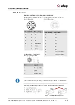
Electrical interfaces of the telescope spindle axis
Pin assignment motor connection Pin assignment encoder connection
(motor side view)
(motor side view).
Pin assignment reference or
Emergency Stop switch
Pin
Signal
1
5 … 24 V DC
3
GND
4
Signal, PNP
We recommend using the Afag standard cables specified in the accessories.
The motor connectors can be rotated 180°. Proceed as described below.
1. Loosen the screws.
2. Rotate the motor connectors.
3. Tighten the screws again.
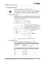
Fig. 9 Adjusting the motor position
SA-3 & SA-6
Base body
A
1
U
B
5
V
C
2
W
D
3
GND Motor
+
6
Brake +
-
4
Brake -
SA-3 & SA-6
Base body
1
S1
2
S3
3
S4
4
S2
5
R1
6
R2
7
Thermo switches
8
Thermo switches
Summary of Contents for 50113773
Page 54: ...54 56 Assembly instructions EN SA 3 I SA 3 FL I SA 6 I SA 6 FL Edition 01 2021 Rev 4 5 ...
Page 55: ...Assembly instructions EN SA 3 I SA 3 FL I SA 6 I SA 6 FL Edition 01 2021 Rev 4 5 55 56 ...
Page 56: ...56 56 Assembly instructions EN SA 3 I SA 3 FL I SA 6 I SA 6 FL Edition 01 2021 Rev 4 5 ...

