Structure and description
24 – 56
Assembly instructions EN
SA-3 I SA-3-FL I SA-6 I SA-6-FL
Edition 01/2021
Rev. 4.5
5 Structure and description
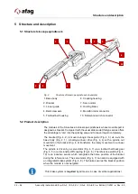
5.1 Structure telescope spindle axis
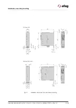
Fig. 4
Structure of telescope spindle axis (example)
1. Base body
6. Coupling housing
2. Bracket
7. Servo motor
3. Linear guide
8. Holding brake
4. Ball screw axis
9. Motor/Encoder connector
5. Toothed belt housing
10. Reference switch connector
5.2 Product description
The modules of the SA series are telescope spindle axis whose movable part is
designed as bracket. Compared with the usual slide model this type series offers
the advantage to “dip” into the working area and to leave it again completely.
The bracket (Fig. 4, 2) is moved along a linear guide (Fig. 4, 3) vis-à-vis the
base body (Fig. 4, 1). A ball-type linear drive (Fig. 4, 4) with a spindle nut
mounted on the bracket (Fig. 4, 2) transforms the rotary movement in a linear
movement.
The spindle is driven by a servomotor (Fig. 4, 7) via a toothed belt back gear
(Fig. 4, 5) or a torsionally stiff coupling (Fig. 4, 6). The reference switch (Fig. 4,
10) is an inductive sensor which recognizes the home position of the bracket
during the reference run. The servomotor (Fig. 4, 7) can also be equipped with
an integrated brake system (Fig. 4, 8). The brake secures the bracket position
when the module is not energized.
This brake system is
required
by all means in case of vertical applications!
10
1
8
4
5
6
7
9
2
3
Summary of Contents for 50113773
Page 54: ...54 56 Assembly instructions EN SA 3 I SA 3 FL I SA 6 I SA 6 FL Edition 01 2021 Rev 4 5 ...
Page 55: ...Assembly instructions EN SA 3 I SA 3 FL I SA 6 I SA 6 FL Edition 01 2021 Rev 4 5 55 56 ...
Page 56: ...56 56 Assembly instructions EN SA 3 I SA 3 FL I SA 6 I SA 6 FL Edition 01 2021 Rev 4 5 ...


