17
21.05 - 6068956_00
NXP 0500 - 1650 2-PIPE SYSTEM / 4-PIPE SYSTEM
EN
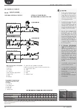
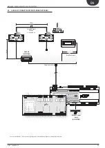
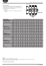
For more informati on, refer to the wiring diagrams in the selecti on program or site www.aermec.com
AUXILIARY CONNECTIONS
(
For Standard Version)
S90CONN*:
cavo di collegamento
BMS
Field-Bus
on/offalar m
enter
I/ O
set
prog.
max 50 m
cavo telefonico
0,
8
m
200 m
S90
CO
N
N
Cavo schermato
AWG24
2 twisted pair
6 5 4 3 2 1 0
6 5 4 3 2 1 0
on/offalar m
enter
I/ O
set
prog.
6 5 4 3 2 1 0
C4
NO8
NO9
NO
10
NO
11
NO
12
RX-/TX-
RX+/TX+
GN
D
Vout
C1
NO1
NO2
NO3
C2
NO4
NO5
NO6
NO7
C3
NC7
G
G0
B1
B2
B3
B4
B5
B6
B7
GN
D
+Vdc
+Vdc
GN
D
+5
Vref
GN
D
Y1
Y2
Y3
Y4
DI1
DI2
DI3
DI4
DI5
DI6
DI7
DIC1
B9
B8
B1
0
B1
1
B1
2
GN
D
ID8
ID9
ID
10
IDC2
J2 - p
robe supply
J3 - analog input
J4 - di
gital input
J5 - analog output
J18 - analog input
J17 - val
ve 2
J16 - di
gital input
J6
J7
J8
J9
J10
J11
J12 -
gr
oup 1
J13 -
gr
oup 1
J14 -
gr
oup 2
J15 -
gr
oup 3
J1 - p
ow
er supply
RX-/TX-
RX+/TX+
GN
D
μPc
200 m
Shielded cable
AWG24
2 twisted pair
Telephone cable
Telephone cable
RS485P1 serial
board
(ACCESSORY)
PGD1 KIT
(ACCESSORY)
10.
AUXILIARY CONNECTIONS(FOR STANDARD VERSION)


