background image

11

21.05 - 6068956_00

NXP 0500 - 1650 2-PIPE SYSTEM / 4-PIPE SYSTEM

EN

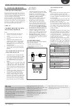
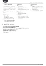
MAIN HYDRAUL IC CIRCUITS

INTERNAL HYDRAULIC CIRCUIT

Model: 

HYDRAULIC COMPONENTS 

RECOMMENDED OUTSIDE THE UNIT

 ATTENTION

..........................................................

1. 

The choice and installation of compo-

nents outside the units is the installer's 

responsibility, who must operate ac-

cording to the code of practice and in 

compliance with the Standard in force 

in the country of destination.

2. 

The hydraulic connection pipes to the 

machine must be suitably  

dimen-

sioned for the effective water flow rate 

requested by the system when run-

ning. The water flow rate to the heat 

exchanger must always be constant.

3. 

Wash the system thoroughly before 

connecting the unit. This cleaning 

operation will eliminate any residues 

such as welding drips, scale, rust, or 

other impurities from the piping. These 

substances can also deposit inside and 

cause machine malfunctioning. The  

connection piping must be adequate-

ly supported so that its weight is not 

borne by the appliance.

4.  An appropriate load/reintegration 

system must be prepared 

(if not in-

stalled),

 which is engaged on the re-

turn line, along with a drain cock in 

the lowest part of the system. Water 

disconnectors must be used in systems 

loaded with anti-freeze or where par-

ticular legal provisions apply. Particular 

supply/reintegration waters must be 

conditioned with appropriate treat-

ment systems. The 

"water features"


provided in the table can be used as a 

reference.

5. 

It is prohibited to release water-glycol 

mixtures into the environment.

6. 

It is recommended to design systems 

with  high  water  content  (minimum 

recommended values shown in table), 

in order to limit:

• 

The hourly number of inversions be-

tween operating modes.

• 

Drop in water temperature during win-

ter defrost cycles.

WATER FEATURES

PH

6-8

Electric conductivity

Less than 200 mV/cm (25°C)

Chloride ions

Less than 50 ppm

Sulphuric acid ions

Less than 50 ppm

Total iron

Less than 0.3 ppm

Alkalinity M

Less than 50 ppm

Total hardness

Less than 50 ppm

Sulphur ions

none

Ammonia ions

None

Silicone ions

Less than 30 ppm

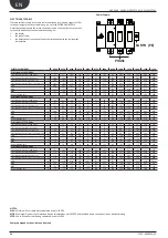
RECOMMENDED MINIMUM WATER CONTENT

NXP WITHOUT PUMPS

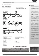
4.  MAIN HYDRAULIC CIRCUIT

5

1

3

6

6

13

13

13

4

4

4

9

2

12

EV

7

7

7

10

11

8

4

9

15

14

6

6

5

5

5

5

5

1

3

13

2

13

4

9

12

REC

7

7

13

10

11

8

4

9

15

4

7

6

6

5

1

3

13

4

13

4

9

12

CN

13

7

7

7

14

15

8

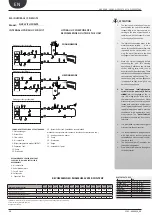
COMPONENTS SUPPLIED AS PER STANDARD

1


- Plate exchanger

5 - Water temperature probes (IN/OUT)

RECOMMENDED COMPONENTS NOT

SUPPLIED FOR WHICH INSTALLER IS RESPONSIBLE

2 - Water filter

3 - Fow switch
4 - Air vent valve

6 - Anti-vibration joints
7 - Cut-off valve

8 - Safety valve

9 - Expansion Tank

Exchanger side (hot/cold)

Exchanger side (DHW)

Exchanger side (geothermal)

10 - 

System buffer tank (installation recommended 

whenever the system water content is less than 
that indicated in tab.)

11 - Antifreeze electric heater

12 - Pump
13 - Drain valve
14 - Gauge

15 - Automatic fill point

NXP 

0500

NXP 

0550

NXP 

0600

NXP 

0650

NXP 

0700

NXP 

0750

NXP 

0800

NXP 

0900

NXP 

1000

NXP 

1250

NXP 

1400

NXP 

1500

NXP 

1650

n°/n°

3/2

3/2

4/2

4/2

4/2

4/2

4/2

4/2

4/2

4/2

4/2

4/2

4/2

l/kW

7

7

7

7

7

7

7

7

7

7

7

7

7

l/kW

14

14

14

14

14

14

14

14

14

14

14

14

14

MINIMUM WATER CONTENT

Compressors / Circuits
System side | Recovery side

RECOMENDED WATER CONTENT

System side  | Recovery side 

(*)Minimum water content for process applications or operating at low external temperatures and low load.

Control on leaving water temperature.

Design Δt less than 5°C.

Summary of Contents for NXP 0500

Page 1: ...21 05 6068956_00 NXP 60Hz 0500 1650 MULTIPURPOSE WATER WATER FOR INDOOR INSTALLATION SCROLL COMPRESSOR PLATE EXCHANGER INSTALLATION MANUAL 60Hz...

Page 2: ......

Page 3: ...k guarantees that our appliances fully comply with the requirements of the European Machinery Directive in terms of safety We constantly monitor the quality level and as a result AERMEC products are s...

Page 4: ...ion on supports 14 9 Electric connections 16 10 Auxiliary connections for standard version 17 11 User interface pgd1 18 12 Displays swichting unit on 19 13 Menu structure and navigation 20 14 Assistan...

Page 5: ...are not respected WARNINGS REGARDING SAFETY AND INSTALLATION STANDARDS 1 Before beginning any operation READ THESE INSTRUCTIONS CAREFULLY AND CARRY OUT THE SAFETY CHECKS TO AVOID ALL RISKS 2 All the s...

Page 6: ...ut sudden movements SELECTION AND PLACE OF INSTALLATION The Units sent from the factory already inspected and only requires electric and hy draulic connections in the place of installation Before begi...

Page 7: ...46 in 2120 mm 1250 mm 2600 mm 49 21 in 102 36 in 795 mm 795 mm 300 mm 300 mm 35 mm 1 38 in 1170 mm 46 06 in 11 81 in 31 30 in 31 30 in 11 81 in 2 95 in 13 98 in 29 72 in 102 36 in 58 66 in DIMENSIONS...

Page 8: ...300 mm 11 81 in 11 81 in 15 94 in 48 11 in 48 11 in 35 mm 1 38 in 1 38 in 1 38 in 35 mm 35 mm 1164 mm 1222 mm 1222 mm 300 mm 405 mm 1202 mm 320 mm 1202 mm 3450 mm 320 mm 405mm 1975 mm 12 60 in 12 60...

Page 9: ...in 2120 mm 83 46 mm 1975 mm 77 76 in 350 mm 1320 mm 1320 mm 13 78 in 350 mm 13 78 in 16 14 in 410 mm 51 97 in 51 97 in 35 mm 1 38 in 35 mm 1 38 in 1320 mm 51 97 in 1320 mm 51 97 in 760 mm 29 92 in 11...

Page 10: ...Victaulic NXP_0500_0750 L 2 1 2 76 1mm 2 1 2 76 1mm 3 88 9mm 3 88 9mm Model Hydraulic Connection Victaulic NXP_0800_1650 Model KEY EV Exchanger side hot cold RC Exchanger side DHW CN Exchanger side g...

Page 11: ...mmended values shown in table in order to limit The hourly number of inversions be tween operating modes Drop in water temperature during win ter defrost cycles WATER FEATURES PH 6 8 Electric conducti...

Page 12: ...able in order to limit The hourly number of inversions be tween operating modes Drop in water temperature during win ter defrost cycles WATER FEATURES PH 6 8 Electric conductivity Less than 200 mV cm...

Page 13: ...ING ATTENTION If the system should stop during the winter period the water present in the exchanger may freeze causing irreparable damage to the exchanger it self There are three solutions possible fo...

Page 14: ...6 0650 without pumps 3 064 4 27 3 60 5 21 23 29 27 0700 without pumps 3 174 7 27 3 61 1 21 24 30 26 0750 without pumps 3 306 9 27 2 65 7 18 27 33 22 AVX365 0800 without pumps 3 505 3 27 1 65 1 18 27 3...

Page 15: ...6 101 7 26 0 73 6 15 24 8 17 27 9 AVX372 1500 max 2 pumps 6 199 7 26 1 73 1 15 24 8 17 27 9 1650 max 2 pumps 6 299 0 26 2 73 2 15 24 8 17 27 9 0500 max 4 pumps 3 461 3 24 8 69 1 21 15 14 21 15 14 AVX...

Page 16: ...ions must be carried out by STAFF IN POSSESSION OF THE NECESSARY QUALIFICATIONS BY LAW suitably trained and informed on the risks related to these operations The features of the electrical lines and o...

Page 17: ...5 4 3 2 1 0 C4 NO8 NO9 NO10 NO11 NO12 RX TX RX TX GND Vout C1 NO1 NO2 NO3 C2 NO4 NO5 NO6 NO7 C3 NC7 G G0 B1 B2 B3 B4 B5 B6 B7 GND Vdc Vdc GND 5 Vref GND Y1 Y2 Y3 Y4 DI1 DI2 DI3 DI4 DI5 DI6 DI7 DIC1 B9...

Page 18: ...ir display The display is made up from a graphical matrix with 132 x 64 pixel in order to signal the type of functioning displaying set parameters and any alarms that have intervened All default se ng...

Page 19: ...i m e s h o w m a s k 20 W a i t p l e a s e 6s A Displays Switching Unit on Unit display Index Display Parameter A Introductory window visible 30 seconds after unit is switched on The seconds remaini...

Page 20: ...Management of the chiller parameters standard energy saving work set point D P1 P1 RECOVERY DHW management parame ters set point consent tem perature time periods etc MAIN SCREEN VISIBLE FOR USER A B...

Page 21: ...rs in cooling mode COLD D 2 PIPES Assistance parameters for the DHW RECOVERY 4 PIPES Assistance parameters in heating mode HOT E NRP FANS Ventilation assistance parameters NXP SOURCE SIDE Pump assista...

Page 22: ...e dure 1 it is possible to scroll the windows that make it up using the arrow keys using the key to pass to the previous parameter and the key to pass to the next parameter previous parameter subseque...

Page 23: ...h the unit Flow switch Pressure switch on closing the cut off valve at the heat exchanger outlet the unit must display the block Finally open the valve and rearm the block MACHINE COMMISSIONING The un...

Page 24: ...ficiency 15 Work pressure 16 Leak test for water tightness control of the cooling circuit 17 Operation of high and low pressure switches 18 Carry out the appropriate checks on the filter dry er to che...

Page 25: ...ce the component Circuit breaker protection intervention Check power supply voltage Check electric isolation of the windings Compressor high discharge pressure High external water temperature High uti...

Page 26: ...current in cooling mode A 42 41 46 51 57 63 84 89 95 108 120 137 154 Total input current in heating mode A 47 48 53 59 67 74 96 102 110 125 139 160 181 Total input current in recovery mode A 47 48 53...

Page 27: ......

Page 28: ...qua VR Italia Tel 39 0442 633111 Fax 39 0442 93577 marketing aermec com www aermec com Aermec reserves the right to make all modification deemed necessary for improving the product at any time with an...

Reviews: