background image


Printed in U.S.A.


  REVISED  JANUARY, 2009 


GF-110


   Instruction 

           No.

AERCO INTERNATIONAL, Inc., Northvale, New Jersey, 07647   USA 


Installation, Operation  

& Maintenance Instructions 
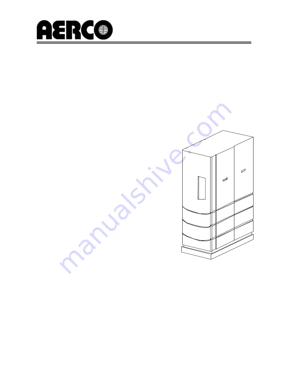


Benchmark


Series 


Gas Fired 
Boiler System


Condensing, Modulating 

 Forced Draft, Hot Water Boiler 

2,000,000 BTU/H Input 

 
Applicable for Serial Numbers G-02-533 and above 
 
Patent # : 2.155.12

Summary of Contents for GF-110 Benchmark Series

Page 1: ...RNATIONAL Inc Northvale New Jersey 07647 USA Installation Operation Maintenance Instructions Benchmark Series Gas Fired Boiler System Condensing Modulating Forced Draft Hot Water Boiler 2 000 000 BTU H Input Applicable for Serial Numbers G 02 533 and above Patent 2 155 12 ...

Page 2: ... warranty of any kind with respect to this material including but not limited to implied warranties of merchantability and fitness for a par ticular application AERCO is not liable for errors appearing in this manual Nor for incidental or consequential damages occurring in connection with the fur nishing performance or use of this material AERCO International Inc 159 Paris Avenue Northvale NJ 0764...

Page 3: ...liary Relay Contacts 2 9 2 9 Flue Gas Vent Installation 2 9 2 10 Combustion Air 2 10 Chapter 3 CONTROL PANEL COMPONENTS AND OPERATING PROCEDURES 3 1 Para Subject Page 3 1 Introduction 3 1 3 2 Control Panel Description 3 1 3 3 Control Panel Menus 3 3 3 4 Operating Menu 3 5 3 5 Setup Menu 3 5 Para Subject Page 3 6 Configuration Menu 3 6 3 7 Tuning Menu 3 7 3 8 Start Sequence 3 7 3 9 Start Stop Level...

Page 4: ...6 Interlock Tests 6 2 6 7 Flame Fault Test 6 3 Para Subject Page 6 8 Air Flow Fault Test 6 4 6 9 SSOV Proof of Closure Switch 6 4 6 10 Purge Switch Open During Purge 6 5 6 11 Ignition Switch Open During Ignition 6 5 6 12 Safety Pressure Relief Valve Test 6 5 Chapter 7 MAINTENANCE REQUIREMENTS 7 1 Para Subject Page 7 1 Maintenance Schedule 7 1 7 2 Spark Igniter 7 1 7 3 Flame Detector 7 2 7 4 Combus...

Page 5: ...sistance Chart C 1 D Indoor Outdoor Reset Ratio Charts D 1 E Boiler Default Settings E 1 App Subject Page F Dimensional and Part Drawings F 1 G Piping Drawings G 1 H Wiring Schematics H 1 I Recommended Periodic Testing Checklist I 1 J Benchmark Control Panel Views J 1 K Benchmark Dual Fuel Propane Switch Over Instructions K 1 WARRANTIES W 1 ...

Page 6: ......

Page 7: ...s the Benchmark ideally suited for modern low temperature as well as conventional heating systems Whether used in singular or modular arrangements the Benchmark offers the maximum flexibility in venting with minimum installation space requirements The Benchmark s advanced electronics are available in several selectable modes of operation offering the most efficient operating methods and energy man...

Page 8: ......

Page 9: ...er by the installer and kept in a safe place for future reference WARNINGS MUST BE OBSERVED TO PREVENT SERIOUS INJURY WARNING BEFORE ATTEMPTING TO PER FORM ANY MAINTENANCE ON THE UNIT SHUT OFF ALL GAS AND ELECTRICAL INPUTS TO THE UNIT WARNING THE EXHAUST VENT PIPE OF THE UNIT OPERATES UNDER A POSITIVE PRESSURE AND THERE FORE MUST BE COMPLETELY SEALED TO PREVENT LEAKAGE OF COMBUSTION PRODUCTS INTO ...

Page 10: ...pstream of the Fill Makeup Valve The vent termination must be located a minimum of 4 feet above grade level If side wall venting is used the installation must conform to the following requirements extracted from 248 CMR 5 08 2 a For all side wall horizontally vented gas fueled equipment installed in every dwelling building or structure used in whole or in part for residential purposes including th...

Page 11: ...ntitled Equipment Not Required To Be Vented in the most current edition of NFPA 54 as adopted by the Board and 2 Product Approved side wall horizontally vented gas fueled equipment installed in a room or structure separate from the dwelling building or structure used in whole or in part for residential purposes c MANUFACTURER REQUIREMENTS GAS EQUIPMENT VENTING SYSTEM PROVIDED When the manufacturer...

Page 12: ......

Page 13: ...als should also be made clear to the delivering carrier 2 2 UNPACKING Carefully unpack the unit taking care not to damage the unit jacket when cutting away packaging materials A close inspection of the unit should be made to determine if there has been any damage not indicated by the Tip N Tell The freight carrier should be notified immediately if any damage is detected The following accessories c...

Page 14: ...pad for proper condensate drainage If anchoring the unit see the dimensional drawings in Appendix F for anchor location Lifting lugs are provided for moving the unit when it has been removed from the shipping skid See Fig 2 2 USE ONLY THE LIFTING LUGS TO MOVE THE UNIT Remove the rear top panel from the unit to provide access to the lifting lugs Remove the four 4 lag screws securing the boiler to t...

Page 15: ...fold drain and the inlet side of the condensate trap Fig 2 5 Secure both ends of the hose with clamps Drainage from the condensate drain trap outlet must be by gravity to a nearby floor drain via a polypropylene hose or suitable piping If a floor drain is not available a condensate pump can be used to remove the condensate to drain The maximum condensate flow rate is 11 GPH The condensate drain tr...

Page 16: ...s and should have no more than 1 droop from minimum to full fire Propane for Dual Fuel Unit The maximum static pressure to the unit must be no more than 14 W C Minimum operating gas pressure for propane is 7 0 W C for FM gas trains and 7 4 W C for IRI gas trains when the unit is firing at maximum input Proper sizing of the gas supply regulator in delivering the correct gas flow and outlet pressure...

Page 17: ...ifferent AC power configurations 220 Vac 1 Phase 60 Hz 20 amps 208 Vac 3 Phase 60 15 amps 460 Vac 3 Phase 60 Hz 15 amps Each of the above power configurations contain a Power Box with a terminal block which matches the configuration ordered The three different terminal block configurations are shown in Figure 2 7 A wiring diagram showing the required AC power connections is provided on the front p...

Page 18: ...graphs Additional information concerning field wiring is provided in paragraphs 2 7 1 through 2 7 9 For additional information on modes of operation refer to Chapter 5 Figure 2 8 I O Box Terminal Location 2 6 1 CONSTANT SETPOINT MODE The Constant Setpoint Mode is used when it is desired to have a fixed setpoint that does not deviate No wiring connections other than electrical supply connections ar...

Page 19: ...s signaling connections are made from the BMS to the RS485 COMM terminals on the I O Box terminal strip Polarity must be maintained and the shield must be connected only at the AERCO BMS The boiler end of the shield must be left floating For additional instructions refer to Chapter 5 paragraph 5 6 in this manual Also refer to GF 108M BMS Model 168 and GF 124 BMS II Model 5R5 384 BMS Operation Guid...

Page 20: ...e North side of the building where an aver age outside air temperature is expected The sensor must be shielded from direct sunlight as well as impingement by the elements If a shield is used it must allow for free air circulation 2 7 2 AUX SENSOR IN The AUX SENSOR IN terminals can be used to add an additional temperature sensor for monitoring purposes This input is always enabled and is a view onl...

Page 21: ...s typically used in conjunction with the auxiliary relay described in paragraph 2 8 This interlock circuit is located in the purge section of the start string It can be connected to the proving device end switch flow switch etc of an auxiliary piece of equipment started by the Boiler s auxiliary relay The delayed interlock must be closed for the boiler to fire If the delayed interlock is connected...

Page 22: ...ill be attached at the blower suction and the knockout at the top of the unit will be and should remain in place The more common methods of supplying combustion air are outlined below For more information concerning combustion air consult the AERCO GF 2050 Venting and Combustion Air Guide 2 10 1 COMBUSTION AIR FROM OUT SIDE THE BUILDING Air supplied from outside the building must be provided throu...

Page 23: ...CTRICAL VOLTAGES IN THIS SYSTEM MAY INCLUDE 460 220 120 AND 24 VOLTS AC IT MUST NOT BE SERVICED OR ACCESSED BY OTHER THAN FACTORY CERTIFIED SERVICE TECHNICIANS WARNING DO NOT ATTEMPT TO DRY FIRE THE BOILER STARTING THE UNIT WITHOUT A FULL WATER LEVEL CAN SERIOUSLY DAMAGE THE UNIT AND MAY RESULT IN PERSONNEL INJURY OR PROPERTY DAMAGE THIS SITUATION WILL VOID ANY WARRANTY 3 2 CONTROL PANEL DESCRIPTI...

Page 24: ...aying up to 16 alphanumeric characters The information displayed includes Startup Messages Fault Messages Operating Status Messages Menu Selection 4 RS 232 Port Port permits a Laptop Computer or External Modem to be connected to the boiler Control Panel 5 FAULT Indicator Red FAULT LED indicator lights when a boiler alarm condition occurs An alarm message will appear in the VFD 6 CLEAR Key Turns of...

Page 25: ...he arrow key will increment the selected setting DOWN Arrow When in one of the main menu categories Figure 3 2 pressing this key will select the displayed menu category If the CHANGE key was pressed and the menu item is flashing pressing the arrow key will decrement the selected setting CHANGE Permits a setting to be changed edited When the CHANGE key is pressed the displayed menu item will begin ...

Page 26: ...ther available data items in the Operating Menu 2 Press the MENU key The display will show the Setup Menu which is the next menu category shown in Figure 3 2 This menu contains the Password option which must be entered if other menu options will be changed 3 Continue pressing the MENU key until the desired menu is displayed 4 With the desired menu displayed press the or arrow key The first option ...

Page 27: ...time language to be used for display messages units of temperature measurements and entries required for external communication and control of the unit via the RS 232 port A view only software version display is also provided to indicate the current Control Box software version NOTE The Outdoor Temp display item shown with an asterisk in Table 3 2 will not be displayed unless the Outdoor Sensor fu...

Page 28: ...aximum Default Internal Setpt Lo Temp Limit Hi Temp Limit 130 F Unit Type Boiler Water Heater Boiler Unit Size 0 5 MBTU 1 0 MBTU 1 5 MBTU 2 0 MBTU 2 5 MBTU 3 0 MBTU 1 0 MBTU Boiler Mode Constant Setpoint Remote Setpoint Direct Drive Combination Outdoor Reset Constant Setpoint Remote Signal If Mode Remote Setpoint Direct Drive or Combination 4 20 mA 1 5V 0 20 mA 0 5V BMS PWM Input Network 4 20 mA 1...

Page 29: ...sure POC switch Low Water Level switch High Water Temperature switch High Gas Pressure switch Low Gas Pressure switch If all of the above switches are closed the READY light above the ON OFF switch will light and the unit will be in the Standby mode When there is a demand for heat the following events will occur NOTE If any of the Pre Purge safety device switches are open the appropriate fault mes...

Page 30: ...rge cycle the Control Box initiates an ignition cycle and the following events occur a The Air Fuel Valve rotates to the low fire ignition position and closes the ignition switch The dial on the Air Fuel Valve Figure 3 6 will read between 25 and 35 to indicate that the valve is in the low fire position b The igniter relay is activated and provides ignition spark c The gas Safety Shut Off Valve SSO...

Page 31: ...e The blower relay will be deactivated and the Air Fuel Valve will be closed Standby will be displayed 3 9 START STOP LEVELS The start and stop levels are the fire rate percentages that start and stop the unit based on load These levels are Factory preset for natural gas as follows Start Level 20 Stop Level 16 Normally these settings should not require adjustment For Dual Fuel units operating on p...

Page 32: ......

Page 33: ... THE BOILER WITHOUT FULL WATER LEVEL THIS CAN SERIOUSLY DAMAGE THE UNIT AND MAY RESULT IN PERSONAL INJURY OR PROPERTY DAMAGE THIS IS NOT COVERED BY WARRANTY CAUTION All installation procedures in Chapter 2 must be completed before attempting to start the unit 4 2 TOOLS AND INSTRUMENTATION FOR COMBUSTION CALIBRATION To properly perform combustion calibration the proper instruments and tools must be...

Page 34: ...the differential pressure regulator see Figure 4 3 2 Place the gasket from the regulator cap onto the regulator adjustment tool 3 Prior to installing the tool on the regulator pull up the screwdriver blade of the tool Then thread the tool into the regulator and hand tighten 4 Engage the tool s screwdriver blade into the regulator s adjustment screw slot Figure 4 3 Differential Regulator Adjustment...

Page 35: ... manometer ensure that there is adequate supply gas pressure If using a non lock up regulator static pressure should be between 9 to 14 WC but no higher than 14 WC If using a lock up style regulator adjust the static supply gas pressure for approximately 9 WC 4 Set the ON OFF switch in the OFF position Turn on AC power to the unit The display will show LOSS OF POWER and the time and date 5 Set the...

Page 36: ...or less 100 ppm 13 Raise the firing rate to 100 Gas pressure should still be 7 0 for FM gas trains and 7 4 W C for IRI gas trains If it is not readjust as necessary 14 Allow the combustion analyzer to settle Compare the measured oxygen level with the levels in Table 3 15 If the measured oxygen reading is within the specified range shown in Table 3 no further adjustment is necessary 16 If the measu...

Page 37: ...c supply gas pressure for approximately 9 WC 6 Set the ON OFF switch to the OFF position Turn on AC power to the unit The display will show LOSS OF POWER and the time and date 7 Set the unit to the Manual Mode by pressing the AUTO MAN key A flashing Manual Fire Rate message will be displayed followed by the present rate in Also the MANUAL LED will light 8 Adjust the rate to 0 by pressing the arrow...

Page 38: ...sure that it is still within the range specified in Table 4 19 Continue this procedure until oxygen levels at 40 24 and 100 firing rates are within the ranges specified in Tables 4 5 and 6 20 Set the ON OFF switch to the OFF position 21 If the unit will be placed into service using propane disregard the following steps and proceed to paragraph 4 5 22 If the unit will be placed into service using n...

Page 39: ...xed manual reset switch that will shutdown and lock out the boiler if the water temperature reaches 210 F The other is an adjustable auto reset switch which allows the boiler to restart once the temperature drops below the temperature setting Figure 4 6 shows the location of the over temperature limit switches Figure 4 6 Over Temperature Limit Switch Location ...

Page 40: ......

Page 41: ...reasing its temperature For instance if a reset ratio of 1 6 is used and we select a building reference temperature of 70 F then at an outside temperature of 69 F the supply header temperature will increase by 1 6 to 71 6 F 5 2 3 Outdoor Air Temperature Sensor Installation The outdoor air temperature sensor must be mounted on the North side of the building in an area where the average outside air ...

Page 42: ...ngs must be made in the Configuration Menu MENU OPTION SETTING Boiler Mode Constant Setpoint Internal Setpt Select desired setpoint using and arrow keys 40 F to 240 F Refer to paragraph 3 3 for detailed instructions on changing menu options 5 4 REMOTE SETPOINT MODES The unit s setpoint can be remotely controlled by an Energy Management System EMS or Building Automation System BAS The Remote Setpoi...

Page 43: ...gnal is present To operate the unit in the Manual mode press the AUTO MAN switch The REMOTE LED will go off and the MANUAL LED will light To change back to the Remote Setpoint mode simply press the AUTO MAN switch The REMOTE LED will again light and the MANUAL LED will go off 5 5 DIRECT DRIVE MODES The unit s fire rate can be changed by a remote signal which is typically sent from an Energy Manage...

Page 44: ...BMS mode is used when it is desired to operate multiple units in the most efficient manner possible The BMS can control up to 40 boilers 8 via pulse width modulation PWM and up to 32 via Modbus RS485 network communication For BMS programming and operation see GF 108M BMS Model 168 and GF 124 BMS II Model 5R5 384 Operation Guide For operation via an RS485 Modbus network refer to the Modbus Communic...

Page 45: ...ad When the combo units are satisfying the domestic load they are in constant setpoint mode of operation When the combo units switch over to space heating their mode of operation changes to the BMS mode For more information concerning the operation of the Combination Control Panel see the AERCO CCP 1 literature 5 7 1 Combination Control System Field Wiring Wiring for this system is between the BMS...

Page 46: ......

Page 47: ... OTHER TESTING PROCEDURES THAT CAN RESULT IN ELECTRICAL SHOCK 6 2 LOW GAS PRESSURE FAULT TEST 1 Referring to Figure 6 1 ensure that the 1 4 leak detection valve located at the high gas pressure switch is closed 2 Remove the 1 4 plug from the 1 4 leak detection valve 3 Install a 0 16 W C manometer or W C gauge where the 1 4 plug was removed 4 Slowly open the 1 4 leak detection valve 5 Place the uni...

Page 48: ...ed error message 11 Set the ON OFF switch to the ON position The unit is now ready for operation 6 5 WATER TEMPERATURE FAULT TEST 1 In the normal operating mode allow the unit to stabilize at its setpoint 2 Lower the adjustable temperature limit switch setting to match the displayed OUTLET TEMPERATURE See Fig 6 2 Figure 6 2 Temperature Limit Switch Setting 3 Once the adjustable limit switch settin...

Page 49: ...erminals remove one side of the jumper If the interlock is connected to a proving switch of an external device disconnect one of the wires leading to the proving switch 4 The unit should shut down and display DELAYED INTERLOCK OPEN The FAULT LED should be flashing 5 Once the interlock connection is reconnected depress the CLEAR button The unit should start 6 7 FLAME FAULT TEST 1 Place the ON OFF s...

Page 50: ...down and display AIRFLOW FAULT DURING RUN 4 Replace the wire previously removed from the blower proof switch and depress the CLEAR button The unit should restart Figure 6 5 Blower Proof Switch Location and Wiring 6 9 SSOV PROOF OF CLOSURE SWITCH 1 Set the unit s ON OFF switch to the OFF position Place the unit in manual mode and set the fire rate between 25 and 30 2 Remove the Safety Shut Off Valv...

Page 51: ...art 6 11 IGNITION SWITCH OPEN DURING IGNITION 1 Set the unit s ON OFF switch to the off position Place the unit in manual mode and set the fire rate between 25 and 30 2 Remove the air fuel valve cover Fig 6 7 by rotating the cover counterclockwise to unlock it then pulling it towards you 3 Remove one of the two wires from the ignition position switch Fig 6 8 and start the unit 4 The unit should be...

Page 52: ......

Page 53: ... igniter contactor and pull the igniter bushing from the burner shell 4 Insert the igniter removal tool into the burner shell where the igniter bushing was removed Fit the hexagonal end of the tool over the igniter See Fig 7 2 Unscrew the igniter from the burner head Remove the igniter from the burner shell by grasping the contact end of the igniter Figure 7 1 Spark Igniter and Flame Detector Loca...

Page 54: ...ay be HOT Allow the unit to cool sufficiently before removing the flame detector To inspect or replace the flame detector 1 Set the ON OFF switch on the control panel to the OFF position Disconnect AC power from the unit 2 Remove the side and top panels from the unit 3 Disconnect the flame detector lead wire Unscrew the flame detector and remove it See Fig 7 2 4 Inspect the detector thoroughly If ...

Page 55: ...the gas outlet side of the Air Fuel Valve See Fig 7 3 NOTE Do not remove the gas inlet pipe from the Burner Assembly See Fig 7 3 7 Remove the six 6 5 16 16 bolts from the burner flange See Fig 7 3 Figure 7 3 Burner Disassembly Diagram NOTE The Burner Assembly is heavy and weighs approximately 25 pounds Use care when removing 8 Remove the Burner Assembly from burner flange by lifting it straight up...

Page 56: ...he trap should be inspected and if necessary cleaned to ensure proper operation Proceed as follows 1 Disconnect the external condensate trap by loosening the hose clamps between the trap and the condensate drain connection on the exhaust manifold of the boiler Figure 2 5 2 Remove the connections on the inlet and outlet sides of the condensate trap shown in Figure 7 5 3 Loosen the four 4 thumbscrew...

Page 57: ...ternal gas supply valve 5 Open relief valve to vent water pressure 7 9 PLACING THE BOILER BACK IN SERVICE AFTER A PROLONGED SHUTDOWN After a prolonged shutdown a year or more the following procedures must be followed 1 Review installation requirements as shown in Chapter 2 2 Inspect all piping and connection to the unit 3 Inspect exhaust vent air duct if applicable and gas regulator vent lines at ...

Page 58: ......

Page 59: ...ion No 1 etc When a fault occurs in the Benchmark Boiler proceed as follows to isolate and correct the fault 1 Observe the fault messages displayed in the Control Box display 2 Refer to the Fault Indication column in the following troubleshooting tables and locate the Fault that best describes the existing conditions 3 Proceed to the Probable Cause column and start with the first item 1 listed for...

Page 60: ... relay is okay check the blower 2 Start the unit If the blower runs check the airflow switch for continuity Replace the switch if there is no continuity 3 Remove the air flow switch and inspect for signs of blockage clean or replace as necessary 4 Inspect the inlet to the combustion blower including any ductwork leading up to the combustion blower for signs of blockage 5 Measure for 24 VAC during ...

Page 61: ...orrectly for the type of signal being sent Check control signal type set in Configuration Menu FLAME LOSS DURING IGN 1 Burner Ground Screw not installed or loose 2 Worn flame detector 3 No spark from Spark Plug 4 Defective Ignition Transformer 5 Defective Ignition Stepper IGST Board 6 Defective SSOV 7 Defective Differential Pressure Regulator 8 Carbon or other debris on Burner 1 Inspect and instal...

Page 62: ...e fault persists replace Ignition Stepper IGST Board 2 Defective relay Replace IGST Board HIGH EXHAUST TEMPERATURE 1 Defective exhaust sensor 2 Carboned heat exchanger due to incorrect combustion calibration 1 Measure the actual exhaust temperature and continuity of the exhaust sensor If the exhaust temperature is less than 475 o F and the exhaust sensor shows continuity replace the sensor 2 If ex...

Page 63: ...Measure the resistance of Shell sensor and BTU sensor at a known water temperature 4 If unit is in Manual Mode switch to Auto Mode 5 Check setpoint of unit and setpoint of Temperature Switch Ensure that the temperature switch is set higher than the unit s setpoint 6 Check the BMS for changes to PID default values correct as necessary 7 If system pump is controlled by Energy Management System other...

Page 64: ...tion 2 Defective ignition switch 3 Defective Power Supply Board or fuse 4 Defective IGST Board 1 Start the unit The Air Fuel Valve should rotate to the purge open position then back to ignition position towards closed during the ignition cycle If the valve does not rotate back to the ignition position check the Air Fuel Valve calibration If calibration is okay the problem may be in the Air Fuel Va...

Page 65: ...2 Test water level circuitry using the Control Box front panel LOW WATER TEST and RESET buttons Replace water level circuitry if it does not respond 3 Check continuity of probe end to the shell change probe if there is no continuity MODBUS COMM FAULT 1 Boiler not seeing information from Modbus network 1 Check network connections If fault persists contact qualified Service Personnel PRG SWTCH CLOSE...

Page 66: ...nsor 1 Inspect Outdoor Temperature sensor for loose or broken wiring 2 Check resistance of sensor to determine if it is within specification 3 Ensure that the correct sensor is installed REMOTE SETPT SIGNAL FAULT 1 Remote setpoint signal not present Not yet installed Wrong polarity Signal defective at source Broken or loose wiring 2 Signal is not isolated floating if 4 to 20 mA 3 Control Box signa...

Page 67: ...he electrical cover from the SSOV and check switch continuity If the switch does not show continuity with the gas valve closed either adjust or replace the switch or actuator 4 Ensure that the SSOV Proof of Closure switch is correctly wired STEPPER MOTOR FAILURE 1 Air Fuel Valve out of calibration 2 Air Fuel Valve unplugged 3 Loose wiring connection to the stepper motor 4 Defective Air Fuel Valve ...

Page 68: ......

Page 69: ... signal supplied to the unit When in the Outdoor Reset Mode this is the derived value from the charts in Appendix D Aux Temp For monitoring purposes only Outdoor Temp Displayed only if an outdoor sensor is installed and enabled in the Configuration Menu Fire Rate In Indicates desired input fire rate This will normally be the same as the fire rate shown on the bar graph fire rate out when the boile...

Page 70: ...ions Baud Rate to be set 2400 to 19 2K Default is 9600 Software Version Identifies the current software version of the control box CONFIGURATION MENU Internal Setpoint Allows internal setpoint to be set Default is 130 F Unit Type Allows selection of Boiler or Water Heater Default is Boiler Unit Size Sets unit size from 0 5 to 3 0 MBTUs Default is 1 0 MBTU Boiler Mode It allows selection of Constan...

Page 71: ...e 40 F to 240 F Any temperature above this setting will turn off the unit The temperature must then drop 5 F below this setting to allow the unit to run Default Temp Hi Limit is 215 F Max Fire Rate Sets the maximum allowable fire rate for the unit 40 to 100 Default is 100 Pump Delay Timer Specifies the amount of time 0 to 30 min to keep the pump running after the unit turns off Default is zero Aux...

Page 72: ...rror is less than the proportional band setting 1 to 120 F the fire rate will be less than 100 If the error is equal to or greater than the proportional band setting the fire rate will be 100 Default is 70 F Integral Gain This sets the fraction of the output due to setpoint error to add or subtract from the output each minute to move towards the setpoint Gain is adjustable from 0 00 to 2 00 Defaul...

Page 73: ...sec Displayed if Demand Delay is active PURGING XX sec Displayed during the purge cycle during startup The duration of the purge cycle counts up in seconds IGNITION TRIAL XX sec Displayed during ignition trial of startup sequence The duration of cycle counts up in seconds FLAME PROVEN Displayed after flame has been detected for a period of 2 seconds Initially the flame strength is shown in After 5...

Page 74: ... air fuel valve closed during purge PRG SWTCH CLOSED DURING IGNITION The Purge Position Limit switch on the air fuel valve closed during ignition AIRFLOW FAULT DURING IGN The Blower Proof Switch opened during ignition AIRFLOW FAULT DURING RUN The Blower Proof Switch opened during run SSOV SWITCH OPEN The SSOV switch opened during standby SSOV FAULT DURING PURGE The SSOV switch opened during purge ...

Page 75: ...setpoint signal is not present or is out of range OUTDOOR TEMP SENSOR FAULT The temperature measured by the Outdoor Air Sensor is out of range OUTLET TEMP SENSOR FAULT The temperature measured by the Outlet Sensor is out of range FFWD TEMP SENSOR FAULT The temperature measured by the FFWD Sensor is out of range HIGH WATER TEMPERATURE The temperature measured by the Outlet Sensor exceeded the Temp ...

Page 76: ......

Page 77: ...APPENDIX C C 1 Temperature Sensor Resistance Chart Balco ...

Page 78: ......

Page 79: ...5F 89 102 115 128 141 154 167 180 193 206 20F 92 106 120 134 148 162 176 190 204 218 Header Temperature for a Building Reference Temperatrure of 60F RESET RATIO Air Temp 0 6 0 8 1 0 1 2 1 4 1 6 1 8 2 0 2 2 2 4 60F 60 60 60 60 60 60 60 60 60 60 55F 63 64 65 66 67 68 69 70 71 72 50F 66 68 70 72 74 76 78 80 82 84 45F 69 72 75 78 81 84 87 90 93 96 40F 72 76 80 84 88 92 96 100 104 108 35F 75 80 85 90 9...

Page 80: ...125 140 155 170 185 200 215 15 113 129 145 161 177 193 209 20 116 133 150 167 201 218 Header Temperature for a Building Reference Temperature of 70F RESET RATIO Air Temp 0 6 0 8 1 0 1 2 1 4 1 6 1 8 2 0 2 2 2 4 70F 70 70 70 70 70 70 70 70 70 70 65F 73 74 75 76 77 78 79 80 81 82 60F 76 78 80 82 84 86 88 90 92 94 55F 79 82 85 88 91 94 97 100 103 106 50F 82 86 90 94 98 102 106 110 114 118 45F 85 90 95...

Page 81: ...0 135 150 165 180 195 210 5F 123 139 155 171 187 203 219 10F 126 143 160 177 194 211 15F 129 147 165 183 201 219 Header Temperature for a Building Reference Temperature of 80F RESET RATIO Air Temp 0 6 0 8 1 0 1 2 1 4 1 6 1 8 2 0 2 2 2 4 80F 80 80 80 80 80 80 80 80 80 80 75F 83 84 85 86 87 88 89 90 91 92 70F 86 88 90 92 94 96 98 100 102 104 65F 89 92 95 98 101 104 107 110 113 116 60F 92 96 100 104 ...

Page 82: ...122 126 130 134 138 65F 105 110 115 120 125 130 135 140 145 150 60F 108 114 120 126 132 138 144 150 156 162 55F 111 118 125 132 139 146 153 160 167 174 50F 114 122 130 138 146 154 162 170 178 186 45F 117 126 135 144 153 162 171 180 189 198 40F 120 130 140 150 160 170 180 190 200 210 35F 123 134 145 156 167 178 189 200 30F 126 138 150 162 174 186 198 210 25F 129 142 155 168 181 194 207 20F 132 146 ...

Page 83: ... Direct Drive or Combination 4 20 mA 1 5V Bldg Ref Temp If Boiler Mode Outdoor Reset 70 F Reset Ratio If Boiler Mode Outdoor Reset 1 2 Outdoor Sensor Disabled System Start Tmp If Outdoor Sensor Enabled 60 F Setpt Lo Limit 60 F Setpt Hi Limit 200 F Temp Hi Limit 210 F Max Fire Rate 100 Pump Delay Timer 0 min Aux Start On Dly 0 sec Failsafe Mode Shutdown mA Output Off Lo Fire Timer 2 sec Setpt Limit...

Page 84: ......

Page 85: ......

Page 86: ......

Page 87: ......

Page 88: ...APPENDIX F F 4 ...

Page 89: ...APPENDIX F F 5 ...

Page 90: ......

Page 91: ......

Page 92: ......

Page 93: ...APPENDIX F F 9 ...

Page 94: ...APPENDIX F F 10 ...

Page 95: ......

Page 96: ......

Page 97: ......

Page 98: ......

Page 99: ...APPENDIX G G 5 ...

Page 100: ......

Page 101: ...APPENDIX H H 1 ...

Page 102: ...APPENDIX H H 2 ...

Page 103: ...1 95 NC T3 A2 303 T3 302 210 RELAY WITH OVERLOAD 260 263 262 261 206 206 300 NEU 200 GROUND BLOCK SHEET 1 OF 2 GND 321 320 TO CONTROL BOX B ADDED GROUND WIRES 320 321 FYP 100703 JM AS FOLLOWS UNLESS OTHERWISE SPECIFIED THIRD ANGLE PROJECTION ALL DIMENSIONS ARE IN INCHES AND ALL TOLERANCES ARE XX 015 XXX 005 FRACTIONS 1 32 ANGLES 1 PERPENDICULARITY PARALLELISM FLATNESS 003 TOTAL DIAMETERS ON A COMM...

Page 104: ...APPENDIX H H 4 ...

Page 105: ...APPENDIX H H 5 ...

Page 106: ...APPENDIX H H 6 ...

Page 107: ...t monthly Operator Visual inspection for condition or obstructions Igniter Weekly Operator see section 7 2 main fuel valve valve position Weekly Operator Check position indicator leakage test annually Service technician Close manual fuel supply valve and test for pressure on down stream valve port Combustion safety flame failure weekly Operator Close manual fuel supply valve check safety shutdown ...

Page 108: ......

Page 109: ...RE P N 124951 V F D DISPLAY MODULE P N 124527 DISPLAY BOARD P N 124365 PMC BOARD P N 124364 LOW WATER CUTOFF BOARD P N 124363 CONNECTOR BOARD P N 124366 IGNITION STEPPER BOARD P N 124361 POWER SUPPLY BOARD P N 124362 GREEN LED P N 124948 ROCKER SWITCH P N 124947 PUSH BUTTON SWITCHES P N 124954 BENCHMARK CONTROL PANEL EXPLODED VIEW ...

Page 110: ...APPENDIX J J 2 P1 P2 P3 P4 P5 P6 BENCHMARK CONTROL PANEL REAR VIEW ...

Page 111: ...ess the Calibration Menu by pressing the MENU key four times 8 Press the arrow key one time Start Level 20 should be displayed indicating that it is currently set for Natural Gas operation 9 Press the CHANGE key The Start Level will begin to flash 10 Press the arrow key and increase the Start Level to 28 11 Press the ENTER key to store the 28 Start Level 12 Press the arrow key again Stop Level 16 ...

Page 112: ...APPENDIX K K 2 FIGURE 1 DUAL FUEL DIVERTER VALVE FIGURE 2 DUAL FUEL AIR INJECTION VALVE ...

Page 113: ...uaranteed against any failure for 18 months from shipment AERCO shall accept no responsibility if such item has been improperly installed operated or maintained or if the buyer has permitted any unauthorized modification adjustment and or repairs to the item The warranty as set forth on the back page of the Operations Maintenance Manual is in lieu of and not in addition to any other express or imp...

Page 114: ...adjustment and or repairs to the item The use of replacement parts not manufactured or sold by AERCO will void any warranty express or limited In order to process a warranty claim a formal purchase order number is required prior to shipment of any warranty item In addition the returned item must include a Returned Goods Authorization RGA label attached to the shipping carton which identifies the i...

Page 115: ......

Page 116: ......

Reviews: