- 16 / 50 -
BN 09 2671/01/01
6 OPERATING INSTRUCTIONS
The following section explains the basic operator menu structure of your system. It allows you to access all
necessary functions in order to operate your system.
The menus, indications and controls available depend on the system configuration.
The keyboard assembly has two LEDs indicators:
green LED: "System OK" (indicates proper operation).
red LED: "Fault" (a fault is present).
The green LED is always on in case no alarms are present.
In case an alarm is present, the red LED comes on and flashes.
If the alarm is acknowledged, the red LED is on permanently provided the alarm is still active.
If no alarms are active after an acknowledgement, the red LED will be switched off and the green LED comes on
again.
6.1 DEFAULT MENU
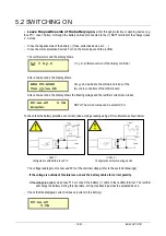
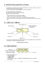
The top line ("DC") will display the charger voltage and the load current with battery shunt or the total charger
current (b load) when the battery shunt is not active.
Hit any key to go to main menu
6.2 MAIN MENU
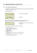
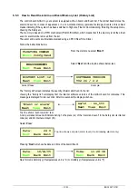
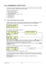
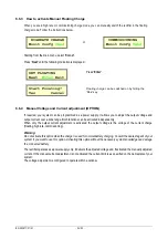
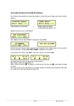
The different rectifier statuses are:
- FLOATING
CHARGE
- HIGHRATE
CHARGE
- COMMISSIONING
- CHARGER OFF (see Chapter 11 "ELEMENTARY TROUBLESHOOTING for more explanations)
- BATTERY
TEST.
DC:XX.XV
XX.XA
FLOATING CHARGE
Monit Confg Cmnd
Output informations
DC output voltage value
DC output current value (this
display value can be
customized )
Number of alarms
Left key menu
Middle key menu
Right key menu
Alarms information
Rectifier status
More than 1 line can be displayed
In this case, end is shown with
“--END OF LIST--” message
Menu keys

