background image


- 25 / 50 - 

BN 09 2671/01/01


How to Adjust the Voltage and Current (Manual Adjustment) 

 
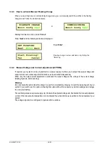
The procedure below explains how to adjust the voltage and current if the manual Voltage and/or Current option is 
activated.  


Current adjustment only activated 

or 

Voltage adjustment activated  


(current adjustment activated or no). 


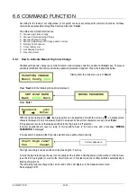
Starting from the main menu, select 

‘Cmnd’


Press 

‘Next’

 until the text ‘ADJUSTMENT’ is displayed and press 

‘Enter’


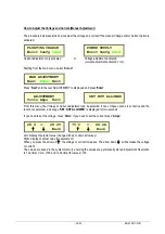
From this menu, the Voltage or Current adjustment can be selected. If one of these options is not active and the 
function is selected, a message 

‘SET. NOT ALLOWED’

 is displayed for two seconds. 

 
If you need to set the voltage, press 

‘Volts’

. If you need to set the current press 

‘Amps’


Left: display of setpoint value (change with up or down arrow key). 
Right: display of actual value (measurement). 
When you press the arrow up 

'

'

 the voltage or current increases. The arrow down 

'

'

 will decrease the voltage 

or current.  
The values are saved in the system memory ensuring the values are permanently stored. Adjustment Resolution 
is 1 decimal V or A <100 and no decimal for values >100. 


FLOATING CHARGE 
Monit Confg 

Cmnd


 MAN.ADJUSTMENT 
Next  

Enter

Exit


   ADJUSTMENT 
Volts Amps  Exit


28.4  <-   28.2V 


Back


75.0   <-  68.2A


Back

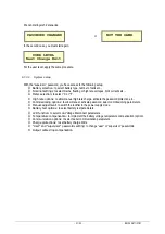
POWER SUPPLY
Monit Confg 

Cmnd


SET NOT ALLOWED 

Summary of Contents for PROTECT RCS

Page 1: ...BN 092671 01 01 07 04 2020 PROTECT RCS Operation manual Battery charger TPRe TD EN ...

Page 2: ...vered equipment is conform with these Directives as long as the user does not change its electrical and mechanical characteristics This equipment is designed to be used in an industrial environment WARNING THIS PRODUCT IS FOR RESTRICTED DISTRIBUTION TO INFORMED INSTALLERS OR USERS INSTALLATION RESTRICTIONS OR ADDITIONAL MEASURES MAY BE NECESSARY TO AVOID DISTURBANCES If the units are equipped with...

Page 3: ...U 16 6 2 MAIN MENU 16 6 3 HUMAN INTERFACE STRUCTURE 18 6 4 STATUS INDICATION DISPLAY 18 6 5 MONITORING FUNCTION 19 6 6 COMMAND FUNCTION 22 6 7 CONFIGURATION FUNCTIONS 29 7 FUNCTIONAL DESCRIPTION 34 7 1 OPERATING SEQUENCES 34 7 2 CHARGE MODES 35 7 3 PRINCIPLE OF OPERATION 35 7 4 GCAU GENERIC CONTROL AND ALARM UNIT A1 36 7 5 TPC THREE PHASE CONTROL BOARD A2 36 7 6 DISPLAY BOARD A300 AND KEYBOARD ASS...

Page 4: ...closed Maintenance personnel door open IMPORTANT RECOMMENDATIONS ANY OPERATION ON THE EQUIPMENT SHOULD BE CARRIED OUT BY QUALIFIED PERSONNEL AWARE OF SPECIFIC ELECTRICAL HAZARDS AND PRECAUTIONS TO BE TAKEN LETHAL VOLTAGES EXIST PERMANENTLY ACROSS THE BATTERY TERMINALS DO NOT MAKE ASSUMPTIONS AS TO THE PRESENCE OR ABSENCE OF A VOLTAGE CHECK USING A VOLTMETER OR AN ELECTRICAL SAFETY TESTER WEEE INFO...

Page 5: ...ECT RCS TPRe TD range offers the following standard ratings and cabinet cooling features PROTECT RCS TPRe TD BATTERY VOLTAGE VDC 24 36 48 60 110 125 127 Output current A Cabinet cooling N natural F forced Cabinet weight kg 20A N 110kg 20A N 110kg 20A N 120kg 20A N 120kg 20A N 220kg 20A N 220kg 25A N 110kg 25A N 110kg 25A N 120kg 25A N 120kg 25A N 220kg 25A N 220kg 40A N 120kg 40A N 120kg 40A N 140...

Page 6: ...ings M1 Common alarm terminal block X12 Charger options marked with Analog rectifier output ammeter P1 Analog rectifier output voltmeter P2 F21 Front panel alarm LEDs A6 8 relays alarm card A5 RS485 modbus communication A71 TCP IP communication for SNMP or Modbus over IP A73 IEC61850 communication A74 Internal DC power supply A30 to energize communication options Internal lighting H7 protected by ...

Page 7: ...cabinet The equipment is fixed onto a pallet 3 1 HANDLING The equipment must be handled with care always in a vertical position Labels on the outside of the package show the top and bottom CAUTION The transport of the system can be performed as follows on pallet by crane in presence of lifting eye bolts by forklift truck ...

Page 8: ...must be used for each eyelet The lifting capacity of the handling equipment used must always be greater than the weight of the cabinets specified on the packages In case of vermin proof plate on the floor the cabinet must be installed using slings CAUTION Only transport the cabinets in an upright position Never tilt or cant always observe the centre of gravity Always keep the battery cells in a ve...

Page 9: ...ocation and the diameter of the fixing holes refer to the customer drawings CAUTION Securing the cabinets to the floor is recommended CAUTION Do not touch the metal section near the heating resistor Do not touch the rectifier bridge heatsinks Installing a single cabinet For the distances between floor fixing hole centers the location and the diameter of the floor fixing holes refer to the product ...

Page 10: ...e period 3 months Storage in seaworthy packing Temperature 25 C to 70 C Relative humidity 15 to 90 in the original package Maximum storage period 12 months For a storage period exceeding the values recommended above contact the factory in order to know the required environmental conditions and the maximum storage duration Operating Temperature 0 C to 50 C Above 50 C and up to 55 C the output curre...

Page 11: ... damaging the control system The external battery shunt must be inserted on the negative polatity of the battery never on the positive polarity as this will damage the charger control board Please contact AEG Power Solutions Customer Service Department 4 1 MAINS INPUT CONNECTION DANGER IF THE RECTIFIER IS EQUIPPED WITH AN OPTIONAL INPUT FILTER MAINS INPUT HIGH LEAKAGE CURRENT EARTH CONNECTION IS M...

Page 12: ...here is an accessible supply of water nearby If electrolyte is splashed wash immediately with water and refer to battery safety data sheets Use tools with insulated handles Remove the shipping plugs from open Ni Cd batteries Always use maintenance accessories especially electrolyte handling tools suited to the batteries Reminder Battery cells must be connected in series the pole of each cell must ...

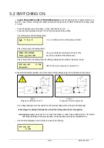
Page 13: ...IMINARY CHECKS All circuit opening devices must be in the open position Check that the mains line protective device rating has the appropriate rating see section 4 1 Check that the mains voltage and frequency are compatible with the equipment see equipment nameplate Check that the mains battery and load connections are tight Check the polarities and that the battery cells are correctly connected i...

Page 14: ...oard After a few seconds the display shows the floating voltage and the rectifier current at no load NOTA The current value can be around 0 5 A To check that the battery polarities are correct take a voltage reading using a DC voltmeter as shown below Case 1 Case 2 Configuration with battery fuse F13 Configuration without opening device The voltage reading must not exceed 30 of the nominal voltage...

Page 15: ...unit 5 4 BATTERY COMMISSIONING CHARGE For open lead acid and Nickel Cadmium batteries at initial start up a commissioning charge can be performed according to the battery manufacturer s instructions refer to the battery manual Open load circuit From the command menu set the rectifier to the commissioning charge refer to paragraph 6 6 2 The initial start up current and time are factory set Refer to...

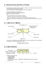
Page 16: ...active after an acknowledgement the red LED will be switched off and the green LED comes on again 6 1 DEFAULT MENU The top line DC will display the charger voltage and the load current with battery shunt or the total charger current battery load when the battery shunt is not active Hit any key to go to main menu 6 2 MAIN MENU The different rectifier statuses are FLOATING CHARGE HIGHRATE CHARGE COM...

Page 17: ... or floating charge Activate commissioning or floating charge Activate or deactivate battery test Clear history entries Menu overview Reset at 100 battery charge level LCD contrast adjust Password English or your local language Enter hour minutes month day and year Voltage and current power supply adjustment Access usually granted with Supervisor password only access rights are factory configurabl...

Page 18: ... Display a selection Enter Acknowledge an entry Exit Always return to default menu The following sections will clearly explain how you can access the various functions 6 4 STATUS INDICATION DISPLAY As explained in the previous chapter the top line of the display will indicate information about the status of the system If more than one message is active the messages are displayed in sequence Each m...

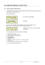
Page 19: ...al for values 100 In order of appearance the following measurements can be displayed Load voltage and current Battery current charge and discharge Battery voltage and total charger current AC input voltage Battery temperature Ambient temperature AH Meter Remaining charge time if in High rate or Commissioning charge Date and Time Customized measurements depends on system configuration Menu can be d...

Page 20: ... View The alarm is shown in clear text on the top line Pressing Next will show you the next alarm in the list and pressing Back will show you the previous alarm in the list If an alarm has not been acknowledged the text Reset will flash If the alarm is acknowledged and the alarm option LCD latch was activated see Alarm Setup for details the alarm will be removed from the list provided the conditio...

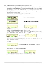
Page 21: ...and Event in the list Viewing the history list will display first the internal software versions of the GCAU board for reference This message is displayed for two seconds After two seconds the display will show Top line shows event or alarm text A non permanent screen will indicate during 1 s the place xx of the alarm and event in the history list its internal code xx and its internal acronym ttt ...

Page 22: ... and with the arrow up an alphanumeric character between 0 and 9 or between A and Z can be set When all four characters are set press Enter If the password is correct the display switches to the High rate on off selection Incorrect passwords will cause a jump of two positions back in the menu tree and a message WRONG PASSWORD is displayed If no password is activated the High rate selection menu wi...

Page 23: ...ng on off selection Incorrect passwords will cause a jump of one position back in the menu tree and a message WRONG PASSWORD is displayed If no password is activated the Commissioning selection menu will be shown directly With Yes the Commissioning charge can be switched on To stop the commissioning charge the user can manually put the rectifier in floating charge mode via the command menu see par...

Page 24: ...age is the voltage of the current charge floating highrate commissioning Warning Do not activate this option when the charger is used for normal battery charging Consult the nearest agent of your system if you want to use this option Activating this option without the necessary system knowledge can damage the connected battery The rectifier operates as a power supply only It delivers the adjusted ...

Page 25: ...nd the function is selected a message SET NOT ALLOWED is displayed for two seconds If you need to set the voltage press Volts If you need to set the current press Amps Left display of setpoint value change with up or down arrow key Right display of actual value measurement When you press the arrow up the voltage or current increases The arrow down will decrease the voltage or current The values ar...

Page 26: ...e instructions below Starting from the main menu select Cmnd Select Next until the following menu is displayed Press Enter If protected by a password enter the password here With the right pointing arrow the digit position can be selected and with the arrow up an alphanumeric character between 0 and 9 or between A and Z can be set When all four characters are set press Enter If the password is cor...

Page 27: ...t pointing arrow the digit position can be selected and with the arrow up an alphanumeric character between 0 and 9 or between A and Z can be set If all four characters are set press Enter When the password is correct the display switches to the Clear History Yes No selection If the password is incorrect a message WRONG PASSWORD is displayed for two seconds and the menu jumps one position back in ...

Page 28: ...ng the Yes key initiates the battery Ah counter to 100 and causes a jump to the default menu Pressing No or Cancel will cause a jump to AH METER 100 menu This manipulation must be always done before a manual battery test 6 6 8 How to Adjust the Display Contrast Adjusting the Contrast from the Default Menu When the contrast is too low to read the display the contrast can be adjusted directly from t...

Page 29: ...the main menu select Confg Select Next until the following menu is displayed Press Enter Press Next until the desired language is shown Pressing the Change key will update the selected language Starting from the main menu select Confg Select Next until the following menu is displayed Select Enter Use the up down arrows to select the set point of hours Hit Enter key to go to next menu Use the up do...

Page 30: ...ccessible to the user the message SET NOT ALLOWED is displayed 6 7 3 1 How to change user and supervisor password Enter the Password setting as follows The first menu is to change the supervisor password PASSWORD SETTING Next Change Exit SUPERVISOR LEVEL Next Change Exit NEW PASSW 1111 Enter FLOATING CHARGE Monit Confg Cmnd SETUP Next Enter Exit Password 1111 Enter SYSTEM SETUP Next Enter Exit BAT...

Page 31: ...ate the password protection etc Commissioning options to allow manual activate password select commissioning parameters Manual adjustment to switch the rectifier in the power supply mode Battery test options to select battery test parameters LVD function to select Low Voltage Disconnect parameters Temperature compensation to implement the battery voltage temperature compensation option Communicati...

Page 32: ...error alarm parameters Internal communication error alarm parameters Battery test failed alarm parameters Battery test abort alarm parameters High battery temperature alarm parameters Long charge time alarm parameters No power supply voltage alarm parameters Battery operation alarm parameters Battery symmetry alarm parameters Service alarms parameters if applicable and activated at factory Procedu...

Page 33: ...ent temperature Battery temperature HIGH MAINS VOLT Next Enter Exit FUNCTION OFF Next Select Next until the required alarm name is displayed then select Enter Example on Charger current limit Select Next until the Function section is reached Use the arrow keys to select ALARM CHARGER CURR LIM Next Enter Exit FUNCTION ALARM Next Select Next until the following menu is displayed CHARGER CURR LIM Nex...

Page 34: ... power ON battery on floating The charger supplies the load Ild and delivers a floating charge current Ifl to battery BT Mains power ON battery recharging The charger recharges battery BT at a high rate Ihr and supplies the load Ild The charger automatically switches to floating charge Ifl when the battery is fully charged Thereafter the battery is kept in floating Ifl Mains power OFF The battery ...

Page 35: ...tors the state of charge of the battery mains off or rectifier in current limiting mode or on Ah drop periodically by the system at fixed intervals 1 month 6 months 1 year depending on factory setting The high rate charge time is factory set to a value in the range from 0 to 99 hours During high rate charge the remaining charge time can be displayed Commissioning charge or boost charge option This...

Page 36: ...C CONTROL AND ALARM UNIT A1 This board has two dedicated microcontrollers memories for the microcontroller and all necessary analog interface circuits to measure and control The board is installed inside the cabinet on charger mounting plate The board consists of two major functional blocks an analog block providing the following main functions analog signal current and voltage matching synchronis...

Page 37: ...purpose 8 OPTIONS The following options are part of the product portfolio and are clasified in two categories Plug in type the option is delivered loose and can be plugged inside the equipment at site Such option might need some settings from the display and keyboard in front of the charger or using the maintenance software Factory Sparc Factory integrated type the option is integrated and tested ...

Page 38: ...ry meter functions if the battery output function is integrated Ibatt meter Ah meter Ibatt Meter If the system is equipped with the battery shunt option and Ibatt Meter is activated the battery charge and discharge currents can be displayed The sign preceding the displayed value indicates a discharge condition In this case the load current will correspond to the rectifier current minus the battery...

Page 39: ...o connect several rectifier systems on one common communication bus centralized supervision of the rectifers to communicate locally or remotely with a computer The rectifiers are acting as slaves and the central computer as the master By giving the different rectifiers different slave numbers it is possible to control each individual rectifier A 2 5 m cable with RJ 6 6 is supplied with this option...

Page 40: ...t breakers are provided for the load lines protection The characteristics of those breakers are 16A C tripping curves 6kA short circuit current 8 3 3 Additional DC filtering Factory integrated type Additional DC filtering additional capacitor or and chokes provides low voltage ripple on DC output without battery When the battery is connected the ripple current of the battery is minimized by the ad...

Page 41: ...f battery current limit display option is not present The output voltage will be increased as a function of the load current This option is used when load cables are connected to a common bus bar on which the battery and the load are connected Voltage measurements on the display Outp measurement menu compensated voltage value from calculation DC default menu and Load measurement menu actual voltag...

Page 42: ...periodic battery test is active as well the periodic timer is reset upon selecting manual battery test to prevent sequential battery tests The time needed to reach the End Voltage level is compared to the time of the previous battery test This previous time is multiplied with a tolerance factor to compensate for battery performance If the time is shorter than this reference time an alarm BATT TEST...

Page 43: ...e battery test the test will be cancelled and the system will return to normal operation when the mains return The Battery test is aborted under the following conditions AC Failure Manual Stop From display serial port or external digital input Discharge current is lower than the required current for 5 minutes In any of these cases the battery test will be aborted and an alarm BATT TEST ABORT is ge...

Page 44: ... Protect RCS is the most reliable one 9 2 PARALLEL SYSTEM CONFIGURATION The paralleling of the systems in not redundant configuration is used to increase of the power of the chargers The paralleling of the systems is used also for increasing the battery capacity when the direct paralleling of the battery strings is not authorised e g VO battery In this case the management of each battery string is...

Page 45: ...aintenance Remove dust Carry out an inspection including the following 1 Disconnect the mains input line and the battery 2 Examine the components and the wiring Pay special attention to signs of overheating and melted insulation Check all connections Check for loose wires 3 Check that the cooling air flow is not impeded clean the fans the air inlets and outlets in case of presence of dust 4 For re...

Page 46: ...red light refer to the following troubleshooting table for the corrective action to be taken NOTE This elementary troubleshooting guide assumes that the usual protective options are fitted Your equipment may be different and some of alarms can be deactivated Refer to the customer drawings ALARM or EVENT PROBABLE CAUSE CORRECTIVE ACTION The display is white Contrast problem Do not touch any button ...

Page 47: ...er output voltage is higher than the maximum allowable value Programmable threshold default value or customer demand value Call the Customer Service Department LOW DC VOLTAGE Low load voltage resulting from rectifier off mains absence or low mains voltage missing phase TPRe Programmable threshold default value or customer demand value Switch on the rectifier Check the mains GROUND FAULT Low resist...

Page 48: ...ing It should not stay more than the usual time charge Otherwise call the Customer Service Department HIGH CHARGR CURR this alarm is disabled by default High charger current Call the customer service department HIGH BATT CURR this alarm is disabled by default High battery current Programmable threshold default value or customer demand value If battery current limit option is activated this alarm s...

Page 49: ...G CHARGE TIME High rate charge time too long Call the customer service department NO PS VOLTAGE No more DC power supply to the board rectifier output voltage out of order Check the fuse F1 Call the customer service department CHARGER OFF It can be due to a normal system operation Alarm activation Serial information input Manual shutdown Initialising delay Put the rectifier in floating charge mode ...

Page 50: ... of the data provided here AEG is a registered trademark used under license from AB Electrolux AEG Power Solutions Parque Tecnológico de Álava I Albert Einstein 31 I 01510 Miñano Álava I Spain I Tel 34 945 214 110 I Fax 34 945 214 111 10 Rue Jean Perrin ZI n 1 I 37170 Chambray Lès Tours I France I Tel 33 2 47 80 88 60 I Fax 33 2 47 28 07 19 I www aegps com Garantiebescheinigung Modell Seriennummer...

Reviews: