4.9 RTC Synchronization
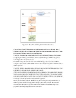
In every ATCA system there are several different clock sources. To avoid differences
in the time values, a synchronization mechanism is needed. (E.g. for timestamps of
the system event logs) This feature helps to determine the master real time clock on
an ATCA board. Following drawing shall give an overview of all ways to get/set the
clocks. The arrows indicate the possible synchronization directions.
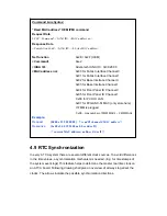
Command Line Syntax:
“Read MAC address” OEM IPMI command
Request Data
b8 00 <Command> <IANA ID> <MAC address no>
Response Data
<Completion Code> <IANA ID> <6 bytes MAC address>
Net function
0x2E / 0x2F (OEM)
<Command>
0xe2
<IANA ID>
Advantech IANA ID = 0x39 28 00
<MAC address no>
0x00 for Fabric Interface Channel 0
0x01
for
Fabric
Interface
Channel
1
0x02 for Base Interface Channel 0
0x03
for
Base
Interface
Channel
1
0x04
for
Front
Panel
IO
Channel
0
0x05
for
Front
Panel
IO
Channel
1
0x06 for PCH IO LAN
0x07 for FPGA NC-SI MAC (only store here)
If FMM is plugged
0x08…max number of FMM MAC’s – FMM MACs
Example:
Request
[b8 00 e2 39 28 00 00] /* read FI channel 0 MAC address */
Response
[bc 00 e2 00 39 28 00 aa bb cc dd ee ff]
/* current MAC address: aa bb cc dd ee ff */
Summary of Contents for MIC-5332
Page 7: ...This page is left blank intentionally ...
Page 10: ...Chapter 1 Product Overview This chapter briefly describes the MIC 5332 ...
Page 15: ...Chapter 2 Board Features This chapter describes the MIC 5332 hardware features ...
Page 43: ...Figure 3 10 Jumper Locations JP1 JP5 JP6 ...
Page 44: ...Chapter 4 Hardware Management This chapter describes the IPMC firmware features ...
Page 105: ... root localhost ipmitool raw 0x2E 0x40 0x39 0x28 0x00 0x03 0x01 section ...
Page 108: ...Appendix A IPMI PICMG Command Subset Supported by IPMC ...
Page 120: ...33 48V_A 48V input feed A 34 48V_B 48V input feed B ...


