Appendix C
Zone 2 Interface pin-out
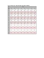
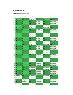
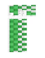
Zone 2 J20 pin out – Update Channel
J20
Pin
Row
A
B
C
D
E
F
G
H
1
N.C.
N.C.
N.C.
N.C.
N.C.
N.C.
N.C.
N.C.
2
Tx4(UP)+
Tx4(UP)
‐
Rx4(UP)+ Rx4(UP)
‐
N.C.
N.C.
N.C.
N.C.
3
Tx2(UP)+
Tx2(UP)
‐
Rx2(UP)+ Rx2(UP)
‐
Tx3(UP)+ Tx3(UP)
‐
Rx3(UP)+
Rx3(UP)
‐
4
Tx0(UP)+
Tx0(UP)
‐
Rx0(UP)+ Rx0(UP)
‐
Tx1(UP)+ Tx1(UP)
‐
Rx1(UP)+
Rx1(UP)
‐
5
N.C.
N.C.
N.C.
N.C.
N.C.
N.C.
N.C.
N.C.
6
N.C.
N.C.
N.C.
N.C.
N.C.
N.C.
N.C.
N.C.
7
N.C.
N.C.
N.C.
N.C.
N.C.
N.C.
N.C.
N.C.
8
N.C.
N.C.
N.C.
N.C.
N.C.
N.C.
N.C.
N.C.
9
N.C.
N.C.
N.C.
N.C.
N.C.
N.C.
N.C.
N.C.
10
N.C.
N.C.
N.C.
N.C.
N.C.
N.C.
N.C.
N.C.
Summary of Contents for MIC-5332
Page 7: ...This page is left blank intentionally ...
Page 10: ...Chapter 1 Product Overview This chapter briefly describes the MIC 5332 ...
Page 15: ...Chapter 2 Board Features This chapter describes the MIC 5332 hardware features ...
Page 43: ...Figure 3 10 Jumper Locations JP1 JP5 JP6 ...
Page 44: ...Chapter 4 Hardware Management This chapter describes the IPMC firmware features ...
Page 105: ... root localhost ipmitool raw 0x2E 0x40 0x39 0x28 0x00 0x03 0x01 section ...
Page 108: ...Appendix A IPMI PICMG Command Subset Supported by IPMC ...
Page 120: ...33 48V_A 48V input feed A 34 48V_B 48V input feed B ...


