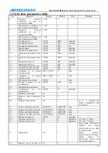
C N C 4 2 2 0 M a c hi ne Too l Op e ra t ion an d Te st
80
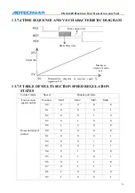
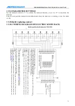
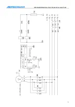
13.10.2
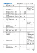
KNIFE REPLACING PARAMETER SETTING
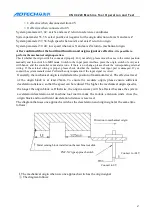
A. No. 46 system knives – Knife station (knife position) number for mechanical turret. Please select
“0” for line knife structure.
B. No. 47 knife position signal level – the effective level of knife position sensor when the knife is in
position
C. No. 48 knife rack lock level – select knife in positive rotation and lock in reverse rotation; the
effective level of lock sensor
D. No. 49 maximum knife replacing time – the time that normal knife rack rotates one circle
E. No. 50 lock delay time – the delay time from the completion of knife selection in positive rotation
to the start of reverse lock
F. No. 51 knife rack reverse lock time – the time required to lock the knife rack
Note: the above parameters are effective to electric knife rack and the line knife doesn’t require the
setting.
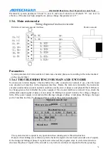
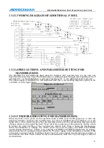
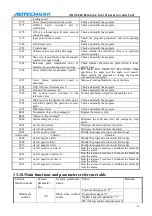
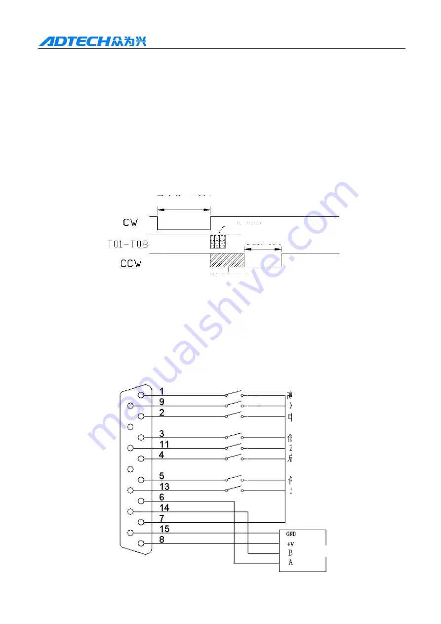
Time sequence figure
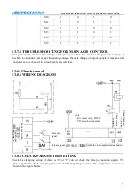
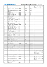
13.10.3
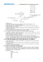
TROUBLESHOOTING FOR KNIFE REPLACING
When the system uses electric turret knife rack, the knife replacing will fail if the parameter setting
isn’t proper, for example, can’t replace the knife. Please check whether the knife number is set to 0,
whether the maximum knife replacing time is reasonable, and whether the settings of connection and
jumper of knife rack signal conversion board are proper. These settings can be checked in the
diagnosis interface. Please reduce the range to eliminate the fault.
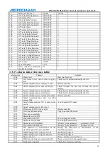
13.11.
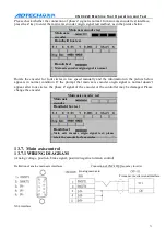
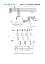
Handheld box and additional panel interface XS7
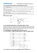
13.11.1
INTERNAL WIRING DIAGRAM OF THE HANDHELD BOX
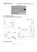
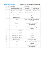
13.11.2
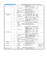
PIN FUNCTION OF HANDHELD BOX INTERFACES
Knife position signal
Lock time
Lock delay
High
X
Medium
Low
Z
Start
Stop
Emergency stop
Encoder