
C N C 4 2 2 0 M a c hi ne Too l Op e ra t ion an d Te st
73
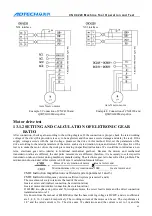
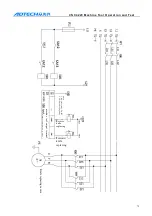
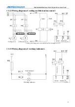
13.7.2
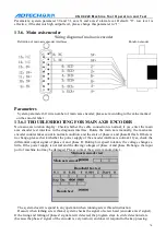
MAIN AXIS PARAMETER SETTING
Main axis control mode (system parameter 58)
Multi-section speed control mode
Two modes are available:
A: Four sections direct output
B: BCD coding output (16-section speed)
Stepless speed regulation mode: analog voltage control mode
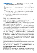
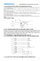
If the parameter value of main axis control mode is set to 0, it is controlled by four-section speed. If
the value is set to 1, it is the stepless speed regulation controlled by analog quantity. If the value is 2, it
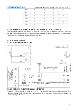
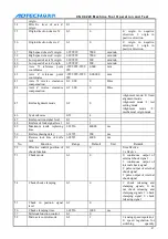
is controlled by 16-section speed. If the value is 3 (DC drive main axis motor stepless speed regulation
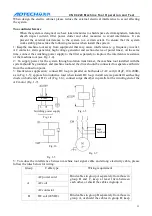
mode), M03 output terminal controls the positive/negative rotation of main DC motor (if the logical
state is 0, the main axis rotates forwardly; if the logical state is 1, the main axis rotates reversely) and
M04 terminal controls the start and stop of main axis. To make the motor rotate, give start signal to the
signal in specified direction. If the output logic of M04 terminal is 1, the main axis is started; if it is 0,
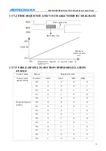
the main axis is stopped. See the table below for the control logic
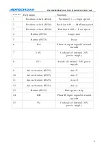
Function
M03 connection end M04 connection end
Main axis forward
rotation M03
1
1
Main axis reverse
rotation M04
0
1
Main axis reverse
rotation M05
Z
0
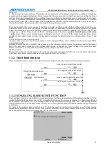
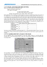
Maximum rotation of main axis (system parameter 59) ---- the maximum rotation (r/min) of the main
axis in analog voltage control mode; this parameter shall match the actual value to get the perfect V/S
linearity.
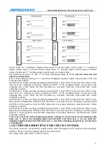
13.7.3
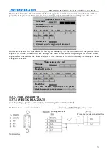
CALIBRATION OF ANALOG VOLTAGE
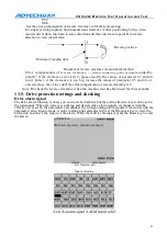
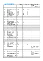
Set the regulation value of system parameter 97 main axis analog voltage to 1, and then press the
parameter key to enter the parameter table of main axis analog quantity, and then switch to MDI mode
and stopped state.
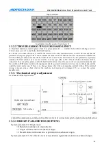
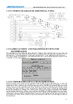
The percentages in the table represent the ratio of theory output voltage and maximum voltage. Press
the direction keys to select a percentage, use a multimeter to record the corresponding voltage and
output to the table in the right. As in the figure above, press the direction key to select 50%, and the
voltage measured with the multimeter is 4.62V. If it is same to the value in the table, it is not
necessary to change. If not, input the measured value into the cell corresponding to 50%.
The system shares two lines of analog voltage, and there are also two calibration parameter tables.
Press the Up/Down key to switch the tables. If the parameters are in disorder, press the Reset key in
MDI mode and stopped state to restore the default values. After the voltage calibration, set parameter
97 to 0.
Main axis analog
quantity parameter table 1
MDI mode