

C N C 4 2 2 0 M a c hi ne Too l Op e ra t ion an d Te st
63
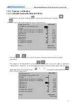
Motor drive test
13.1.2
SETTING AND CALCULATION OF ELETRONIC GEAR
RATIO
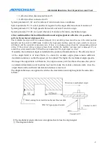
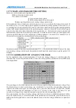
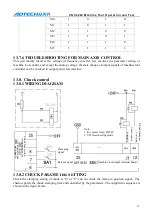
After connection, check again according to the wiring diagram. If the connection is proper, check the rated working
voltage of the drive (this procedure is easy to be neglected, and thus cause severe damage and delay the test). If the
supply voltage accords with the rated voltage, please set the drive in this method: First, set the parameters of the
drive according to the rated parameters of the motor, such as rated rotation, torque and current. The objective of the
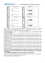
test is to make the motor drives the work piece moving in specified instructions. We would like to introduce a new
term, electronic gear ratio (similar to functional mechanical gearbox). Because the motors and mechanical
transmission ratios are different, the unit pulse movements are different; therefore, it is necessary to select specific
transmission ratio and motor during machinery manufacturing. The electronic gear ratio has solved this problem. The
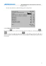
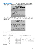
minimum instruction unit of this system is 0.001mm. A calculation formula follows:
CMR: Instruction magnification coefficient (system parameter 1 and 3)
CMD: Instruction fre
quency division coefficient (system parameter 2 and 4)
The movement of every rotation is the lead of the screw
Gears at screw end (indirect connection, has rotation ration)
Gears at motor end (indirect connection, has rotation ration)
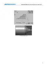
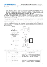
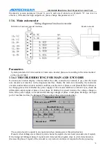
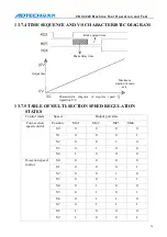
If 403BM two-phase step drive and 56 two-phase motor, the screw lead is 4mm and the direct connection
transmission ratio is 1:1
It is known from the manual of 403BM drive that the base working voltage is DC40V, and six coefficients
are 2, 4, 8, 16, 32 and 64 respectively. The working current of the motor can be set. The step distance is
1.8° and the rated current is 3A. The drive uses 32 subdivisions and the current is set to 3A, and the
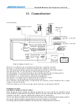
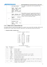
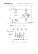
XS1 interface
A
xi
s X
s
er
vo m
ot
o
r dr
iv
e
Axis X servo motor
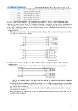
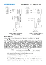
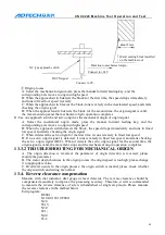
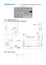
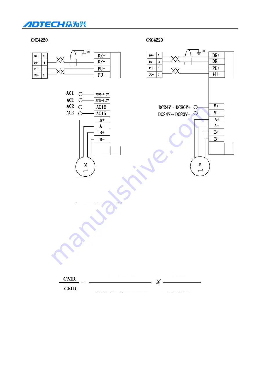
Example 3: Connection of CNC4220 and
Q2BYG1106M step drive
Axis X servo motor
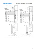
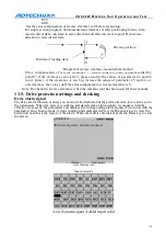
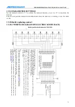
Example 4: Connection of CNC4220 and
Q2BYG808M step drive
Pulses of every rotation of motor Gear at screw end
Motion distance of every rotation mm*1000 Gear at motor end
A
xi
s X
s
er
vo m
ot
o
r dr
iv
e
XS1 interface