C N C 4 2 2 0 M a c hi ne Too l Op e ra t ion an d Te st
76
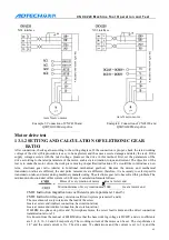
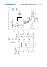
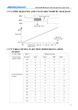
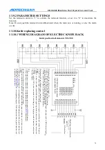
Chuck mode “0”: continuous output control mode of internal chuck; chuck mode “1”: continuous
output control mode of external chuck; chuck mode “2”: inching output control mode of internal
chuck; chuck mode “3”: inching output control mode of external chuck
The difference between “0” and “2” of chuck clamping settings:
if “2” is selected, main axis and
chuck are interlocked.
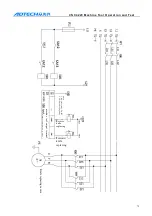
If the chuck clamping setting is “1”, check the clamping in position signal. The principle of the four
working mode follows:
Chuck mode 0: while executing clamping instruction M12, open XS6-12 port and close XS6-13 port,
and check the clamping in position signal pin XS5-8. If the clamping signal is detected in the
clamping time of the chuck, the M12 instruction is executed; otherwise, send alarm info “chuck
clamping overtime”.
Chuck mode 1: while executing clamping instruction M12, open XS6-13 port and close XS6-12 port,
and check the clamping in position signal pin XS5-7. If the clamping signal is detected in the
clamping time of the chuck, the M12 instruction is executed; otherwise, send alarm info “chuck
clamping overtime”.
Chuck mode 2: while executing clamping instruction M12, open XS6-12 port and close XS6-13 port,
delay chuck clamping time and then clock the XS6-12 port, and check the clamping in position signal
pin XS5-8. If the signal is valid, the M12 instruction is executed; otherwise, send alarm info “chuck
clamping overtime”.
Chuck mode 3: while executing clamping instruction M12, open XS6-13 port and close XS6-12 port,
delay chuck clamping time and then clock the XS6-13 port, and check the clamping in position signal
pin XS5-7. If the signal is valid, the M12 instruction is executed; otherwise, send alarm info “chuck
clamping overtime”.
Note: when check the chuck clamping parameter settings: 0- do not check, do not interlock with
main axis, 1- check the clamping signal and interlock with main axis, 2- do not check the
clamping signal but interlock with main axis, 3- check the clamping signal but do not interlock
with main axis
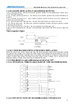
13.8.3
TROUBLESHOOTING FOR CHUCK CONTROL
The chuck control is comparatively simple and its main I/O signals can be checked in the diagnosis
interface. Please check the relating signal if any fault occurs.
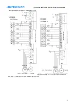
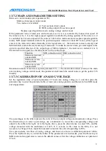
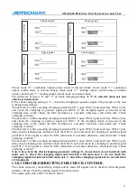
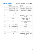
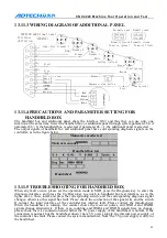
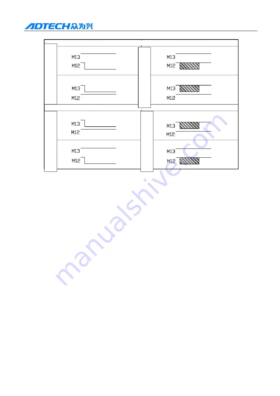
The output point state of M12 is shown below.
Chuck mode 0 | Chuck mode 2
Chuck mode 1 | Chuck mode 3
C
la
m
pe
d
|
R
el
ea
se
d
C
la
m
pe
d
|
R
el
ea
se
d
C
la
m
pe
d
|
R
el
ea
se
d
C
la
m
pe
d
|
R
el
ea
se
d