


Hybrid Standalone NVR User Guide
3.8.8.10
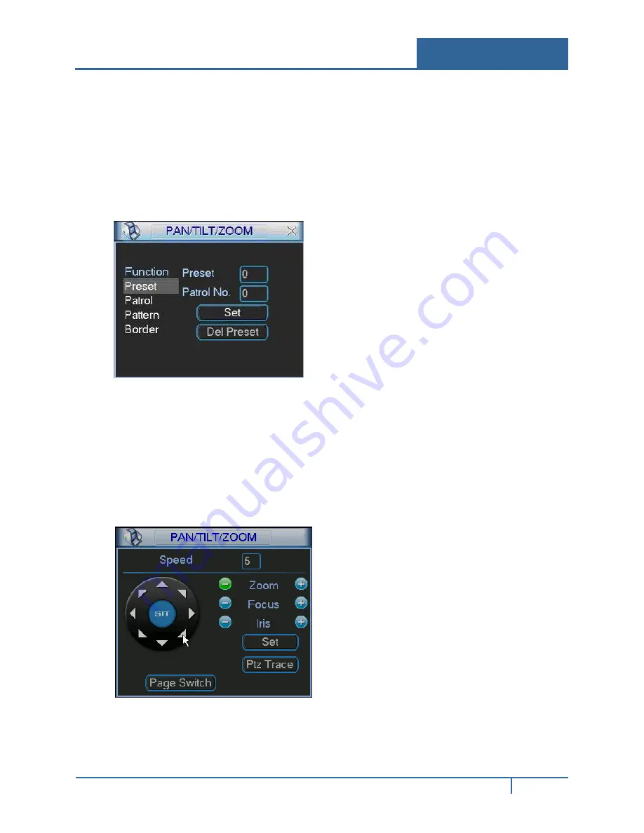
Set Button
Click the
Set
button in the Main PTZ screen shown in Figure 3-82. The setup dialog appears. Here
you can set the following items:
•
Preset
•
Patrol
•
Pattern
•
Border
Presets
Presets are programmed locations that the PTZ camera is trained to view. These presets can be
strung together to move the camera in a designed movement called a Patrol.
To setup the Preset:
1.
In the Main PTZ Control screen, use the eight direction arrows to adjust camera to the proper
position.
NVR32xx-P Series User Guide
99


