background image

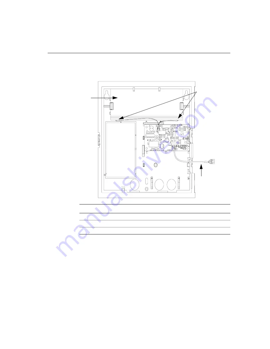
Disconnecting and Removing a Series 400 Timeclock

Series 4000 Badge Timeclock Installation Guide

A-5

b. Disconnect the battery charger board from the timeclock’s main board 

(inside the cover).

9. Remove the three mounting screws in the base of the timeclock to remove the 

timeclock from the wall. The screws are located in the top left and right 
corners, and the bottom middle of the base.

You are now ready to install the Series 4000 timeclock. For detailed instructions, 
go to Chapter 2, “Installing the Series 4000 Timeclock.”

Number

Description

1

Battery

2

Battery charger board connections to the backup battery

3

Battery charger board connection to the main board

1

3

2

Summary of Contents for Series 4000

Page 1: ...evision B Series 4000 Installation Guide Series 4000 Badge Timeclock Presents instructions for installing the Series 4000 badge timeclock and performing basic configuration Includes instructions for troubleshooting installation related problems ...

Page 2: ... Adaptive Server is a trademark of Sybase Inc iSeries and WebSphere are trademarks and AIX AS 400 and IBM are registered trademarks of International Business Machines Corporation Lotus and 1 2 3 are registered trademarks of Lotus Development Corporation Carbon Copy and OpenVMS are trademarks of Compaq Computer Corporation pcAnywhere is a trademark of Symantec Corporation Cognos Impromptu and Power...

Page 3: ...nce with FCC regulations shielded cables must be used with this equipment Operation with non approved equipment or unshielded cables is likely to result in interference to radio and television reception Canadian DOC Compliance This digital apparatus does not exceed the Class A limits for radio noise emissions from digital apparatus set out in the Radio Interference Regulations of the Canadian Depa...

Page 4: ......

Page 5: ...ck 1 7 Chapter 2 Installing the Series 4000 Timeclock Preparing the Location of the Timeclock 2 2 Preparing a Location Over an AC Outlet 2 2 Preparing a Location to Use an Internal AC Outlet 2 3 Preparing a Location Near an AC Outlet 2 4 Widening the Badge Reader Slot optional 2 5 Mounting the Base of the Timeclock 2 8 Running Cables Into the Timeclock 2 10 Assembling the Timeclock 2 12 Installing...

Page 6: ...erview 3 2 Parts of the Timeclock 3 2 Guidelines for Entering Information Using the Timeclock 3 4 Completing Configuration Screens 3 5 Completing the Timeclock Configuration 3 9 Other Series 4000 Documentation 3 10 Chapter 4 Troubleshooting Hardware and Operational Problems Appendix A Replacing a Series 400 Timeclock with a Series 4000 Timeclock Read This First A 2 Disconnecting and Removing a Ser...

Page 7: ... mylar strip from the lithium battery on the inside cover of the timeclock See page 2 21 _____ Plug in the Series 4000 timeclock and verify that it is operating properly See page 2 21 _____ Perform local configuration at the Series 4000 timeclock See page 3 1 _____ Add the Series 4000 timeclock as a device in your ADP system For guidance based on the host application you are using see page 3 9 ___...

Page 8: ...Checklist of Installation and Configuration Tasks viii ADP Inc ...

Page 9: ...Before You Install the Series 4000 Timeclock This chapter contains the following sections Unpacking and Inspecting the Timeclock Determining Where to Install the Timeclock Tools Required to Install the Timeclock ...

Page 10: ...eries 4000 Timeclock 1 2 ADP Inc Unpacking and Inspecting the Timeclock Carefully remove the contents from the box Refer to the following illustration and the listing on the next page to ensure you have all of the parts of the timeclock ...

Page 11: ...boxes and with their own installation instructions Number Part 1 Cover assembly including an integral bar code reader 2 Base of the timeclock and hinge 3 Power cord strain relief clip with two screws and two nuts packed with other accessories in a plastic bag 4 Security wrench three pointed mounting screws three anchors and two flat screws not pointed 5 Transformer 6 Plate and two nuts to convert ...

Page 12: ...all this method secures the power connection inside the timeclock For instructions about determining the location of the AC outlet and timeclock see page 2 2 Install an internal AC outlet If you cannot mount the timeclock over an AC outlet for example if you are mounting the timeclock on masonry use the internal AC outlet option purchased separately from ADP This method secures the power connectio...

Page 13: ...all You must mount the timeclock directly to the wall Environmental Considerations Consider the following when deciding where to install the Series 4000 timeclock The timeclock is designed for mounting on walls in typical office and indoor manufacturing environments Recommended wall surfaces are drywall sheetrock and wood The timeclock can withstand the following temperature and humidity ranges Te...

Page 14: ...he timeclock run the cable before you install the timeclock Ensure that the cable exits the wall at a point where it can enter the installed timeclock and that you provide at least 20 inches 50 8 cm of slack from the point of entry into the timeclock Instructions for marking the point of entry into the timeclock are presented in Preparing the Location of the Timeclock beginning on page 2 2 To conn...

Page 15: ...ll the Timeclock Series 4000 Badge Timeclock Installation Guide 1 7 Tools Required to Install the Timeclock Tape measure Level Electric drill Utility knife Phillips screwdriver Security wrench ships with timeclock Keyhole saw ...

Page 16: ...Chapter 1 Before You Install the Series 4000 Timeclock 1 8 ADP Inc ...

Page 17: ...e Series 4000 Timeclock This chapter contains the following sections Preparing the Location of the Timeclock Mounting the Base of the Timeclock Assembling the Timeclock Supplying Power to the Timeclock and Verifying Operation ...

Page 18: ...w large amounts of power such as air conditioning units electrical motors and compressors Also avoid running communications cable near devices that interfere with data transmission Attention Vous devez faire appel à un électricien agréé pour installer la prise c a avant d installer le terminal Series 4000 La source utilisée pour alimenter le terminal doit être munie d un dispositif de disjonction ...

Page 19: ...o Use an Internal AC Outlet 1 Tape the mounting template at the desired height and location for the timeclock The top two mounting screws must be no higher than 54 and 3 8 inches 138 09 cm above the floor 2 Mark the location of the mounting screw holes 3 If you will run an AC power line through the wall and into the timeclock mark the cable s point of entry into the timeclock as indicated on the t...

Page 20: ... 1 Select a location where the distance from the knockout for the power cable at the bottom of the timeclock to the AC outlet is not more than 5 feet 152 40 cm Also the top two mounting screws must be no higher than 54 and 3 8 inches 138 09 cm above the floor 2 Tape the mounting template at the desired height and location 3 If you plan to run the Ethernet cable through the wall to enter the timecl...

Page 21: ...rnet cable through the wall at the point of entry into the timeclock Provide 20 inches 50 8 cm of slack Widening the Badge Reader Slot optional If the badges you will use with the timeclock are more than 050 in 1 27 mm thick you need to install two spacers in the badge reader to accommodate the badges Otherwise go to Mounting the Base of the Timeclock on page 2 8 The spacers are molded into the ba...

Page 22: ... 1 Use a utility knife to remove the spacers from the base 2 Use a Phillips screwdriver to loosen the two captive screws inside the timeclock cover that hold the badge reader cover in place Number Description 1 Screws that hold the badge reader cover in place ...

Page 23: ...3 On the outside of the timeclock cover press the two spacers onto the tops of the channels that hold the screws for the reader cover See the following illustration 4 Position the reader cover back into place and tighten the two screws Number Description 1 Badge reader spacers 2 Reader cover ...

Page 24: ...following procedure to mount the base of the timeclock to the wall 1 If you are installing the timeclock over an AC outlet remove the knockout in the base of the timeclock Do this by cutting the plastic tabs with a keyhole saw Refer to the following illustration for the location of the knockout Number Description 1 Knockout for AC outlet plastic tabs indicated by X ...

Page 25: ...rywall do the following a Use a 9 32 inch drill bit 7 1 mm to drill holes for the wall anchors b Install the wall anchors c Install the top two screws leaving 1 4 inch 6 mm between the head of the screw and the wall 3 Align the top two screw holes in the base of the timeclock with the screws in the wall and gently set the base in position 4 Tighten the top two screws 5 Install and tighten the bott...

Page 26: ...of the timeclock has cable access holes in the top right portion of the base and in the metal plate at the bottom of the base See the following illustration Number Description 1 Access holes for running cables into the back of the timeclock 2 Access holes for running cables into and out of the timeclock ...

Page 27: ...duit by pressing on it firmly and carefully 2 Install a cable clamp in the conduit opening 3 Run the cable through the clamp providing the following slack AC power line 12 inches 30 48 Ethernet cable 11 inches 27 94 cm 4 Tighten the screws on the clamp to secure the cable The following illustration shows how your cable routing should look Callout 1 indicates the location of the cable clamp assembl...

Page 28: ...g the Optional Internal AC Outlet If this timeclock will use an internal AC outlet refer now to the instructions in the Internal AC Outlet Option Kit Installation Guide that you received with the option kit Before you begin the internal AC outlet installation ensure that power to the AC line is shut off When you finish installing the internal AC outlet follow the instructions under What To Do Next...

Page 29: ... the transformer Use the 12 inch 30 48 cm cord if you mounted the timeclock over an AC outlet or are using the internal AC outlet option Use the 6 foot 182 88 cm cord if you are using an external AC outlet The following illustration shows the 12 inch power cord 2 Position the transformer behind the wire clip in the timeclock base ...

Page 30: ...s to secure the cord Assemble the strain relief clip nuts and screws as shown in the following illustration If you did not use the square cable access hole in the bottom of the terminal to run the power cable cover the access hole using the square black plate and two nuts that shipped with the terminal To do this a Slip the square plate over the screw posts located at two corners of the access hol...

Page 31: ... Installation Guide 2 15 Attaching the Timeclock Cover to the Base 1 Release the plastic hinge clip by squeezing the retainers at each hinge position Squeeze each retainer one at a time until you feel the clip release 2 Rotate the hinge clip to the left ...

Page 32: ...Installing the Series 4000 Timeclock 2 16 ADP Inc 3 Fit the two hinges on the cover into the corresponding areas molded in the base Number Description 1 Recessed areas in the timeclock base for seating the hinges ...

Page 33: ... Timeclock Installation Guide 2 17 4 Carefully close the cover of the timeclock making sure that the two hinges remain properly seated in place Caution After the cover is closed continue to hold it securely in place as you perform the next step ...

Page 34: ...e Series 4000 Timeclock 2 18 ADP Inc 5 Rotate the hinge clip forward until it snaps into place 6 Open the cover and install the two small flat not pointed screws to secure the hinge clip as shown in the following illustration ...

Page 35: ...rnet cable if you ran the cable through the wall and into the back of the timeclock Use the hooks molded into the base of the timeclock to secure the cable along its route Also avoid excessive bending or crimping of the cable Number Description 1 Ethernet cable through the wall and into the back of the timeclock 2 Ethernet connection to the timeclock s main board ...

Page 36: ...0 Timeclock 2 20 ADP Inc The following illustration shows how to connect the Ethernet cable if you ran the cable through the bottom of the timeclock Number Description 1 Ethernet cable 2 Ethernet connection to the timeclock s main board ...

Page 37: ...trations in this section assume that you have installed the backup battery and that you ran the Ethernet cable through the wall and into the back of the timeclock However the procedure in this section applies to all installation scenarios Supplying Power to the Timeclock 1 Remove the mylar strip from the lithium battery located on the main board in the cover of the timeclock ...

Page 38: ... the cable up the left side of the transformer as shown in the following illustration Use the hooks molded into the base of the timeclock and the channel along the top of the cover to secure the cable along its route Number Description 1 Transformer cable 2 Hooks for routing the cable 3 Transformer connection to the main board DC power ...

Page 39: ...on Series 4000 Badge Timeclock Installation Guide 2 23 3 If you installed the battery connect the charger board to the main board Number Description 1 Battery charger board cable that connects to the main board 2 Charger board connection to the main board ...

Page 40: ...he cord in now Note When the Series 4000 timeclock is first powered and running the optional backup battery is not yet charged It takes approximately 24 hours for the battery to fully charge itself 5 Close the cover of the timeclock enough so that you can view the display screen as the timeclock initializes itself Over an AC outlet top receptacle Using an internal AC outlet ...

Page 41: ...he operating system and timeclock application This process takes approximately one minute If the initialization completes successfully the Communications Setting screen appears Go to page 2 26 then to Chapter 3 Performing Local Configuration If the Communication Setting screen does not appear the timeclock did not initialize successfully Contact your TLM Representative Device ID Changing comm sett...

Page 42: ...ck it using the security wrench to tighten the security screw on the cover Caution When you close the cover ensure that you are not closing it on any of the cables inside the timeclock Do not force the cover when closing it You are now ready to configure the timeclock Go to Chapter 3 Performing Local Configuration Number Description 1 Security screw 2 Security wrench ...

Page 43: ...Chapter 3 Performing Local Configuration This chapter contains the following sections Configuration Process Overview Completing Configuration Screens Completing the Timeclock Configuration ...

Page 44: ...time and date and the appearance of the display You must perform local configuration first Remote configuration Includes defining which functions and transactions users can perform at the timeclocks You use the host application to configure the timeclock Note This chapter explains how to perform local configuration only Parts of the Timeclock The following illustration shows the parts of the Serie...

Page 45: ...een that displays soft key labels possible functions transaction steps and transaction output 5 LEDs Visual indicators The top LED is green and flashes when the timeclock successfully reads a badge that is swiped by a user The middle LED is amber and flashes when the timeclock does not successfully read a badge that is swiped by a user The bottom LED is amber and indicates whether the timeclock is...

Page 46: ...ine of the text box and a flashing cursor If you enter characters in a field that already contains data the existing data is not overwritten it is pushed to the right To remove individual characters position the cursor immediately to the right of the characters and press the Backspace key To clear all characters in a field press the CLR key If you complete a field incorrectly and move to the next ...

Page 47: ...n ID number at least six digits for the timeclock The host application uses this number to identify the timeclock IP Address Enter the IP address including the periods assigned to the timeclock by your system administrator Gateway Enter the IP address including the periods of the default device that forwards data to the host application This field holds up to 15 digits Subnet Mask Specify a number...

Page 48: ... 4000 timeclock the badge has an M on the front To do this hold the badge so that the bar code is positioned on the back left edge and swipe the badge up or down through the reader s slot The Maintenance Mode menu screen appears Fri 17 Aug 2001 2 03 PM Comm Setting Display Setting Audio Setting Symbology Setting Date Time Setting Maintenance Mode 2 03 PM FACTORY DEFAULT Restart More Fri 17 Aug 200...

Page 49: ...ttom of the screen to increase or decrease the degree of difference between light and dark extremes of color on the timeclock s display The minimum value is 16 the maximum value is 22 Brightness Use the and keys indicated at the bottom of the screen to increase and decrease the brightness of the timeclock display Settings Description Beeper volume Use the and keys indicated at the bottom of the sc...

Page 50: ...word that allows access to the Maintenance Mode screen in the future press the More soft key and then the Change Password soft key Complete the following fields 13 Press ENTER to save the password and return to the Maintenance Mode screen 14 Press ESC to exit Maintenance Mode and return to the idle screen Settings Description Old Password Enter the old password if there was one New Password Enter ...

Page 51: ...eclocks New See the eTIME Configuration Manager Reference and the online Help Enterprise eTIME In DCM use the Device Wizard or Advanced Device Manager See the Data Collection Manager System Administrator s Guide and the online Help Host application What to do eTIME Use Configuration Manager to test communication as part of adding a timeclock See the eTIME Configuration Manager Reference and the on...

Page 52: ...em Administrator s Guide and the online Help Host application What to do eTIME Use the Configuration Manager to download the necessary data to the timeclock based on the transactions you set up Timeclocks Timeclocks select a terminal click the arrow next to the Open button and select Download Options See the eTIME Configuration Manager Reference and the online Help Enterprise eTIME Workforce Smart...

Page 53: ...ck s main board the AC outlet or both Check the connections to the main board and the AC outlet Important If the power cord is not plugged into the AC outlet do not plug it in until you ensure that the transformer is properly connected to the main board For instructions see Supplying Power to the Timeclock beginning on page 2 21 The power LED is turned on but nothing appears on the screen The AC l...

Page 54: ...using a code Correct the badge reader and company ID code settings If your host application is Enterprise eTIME use the Data Collection Manager DCM if your host application is eTIME use Configuration Manager The badge reader may not be working correctly Run the Badge Test test at the timeclock 1 Access Maintenance Mode 2 On the Maintenance Mode screen press the More soft key to display the test fu...

Page 55: ... ID IP Address Gateway and Subnet Mask settings If communication continues to fail check the communication settings at the host PC Refer to the documentation for your ADP host application Communications cabling is connected incorrectly Ensure that all communications cables are routed correctly and connected properly If the connections are secure determine whether the cable is defective by doing th...

Page 56: ...Chapter 4 Troubleshooting Hardware and Operational Problems 4 4 ADP Inc ...

Page 57: ...Appendix A Replacing a Series 400 Timeclock with a Series 4000 Timeclock This appendix contains the following sections Read This First Disconnecting and Removing a Series 400 Timeclock ...

Page 58: ...lock and the Series 4000 timeclock are identical You can install the Series 4000 timeclock in exactly the same location as the timeclock you are replacing However ensure that the location satisfies the following requirements To comply with the Americans with Disabilities Act ADA the top of the timeclock cannot be greater than 54 and 3 8 inches 138 09 cm above the floor If the Series 4000 timeclock...

Page 59: ...f the timeclock using the hex wrench that came with the Series 400 timeclock to loosen the security screw on the left side of the cover 3 Carefully open the cover of the timeclock 4 Disconnect the timeclock from its AC power source Depending on how the timeclock was installed do one of the following Unplug the power cord from an AC outlet external to the timeclock If the timeclock was mounted to c...

Page 60: ... If the Ethernet cable was routed through the bottom of the timeclock remove the cable from inside the timeclock 8 If the timeclock has a backup battery disconnect the battery as follows Refer to the following illustration as you perform these steps a Disconnect the battery charger board from the terminals on the backup battery Number Description 1 Ethernet board 2 Main board 3 Ethernet connection...

Page 61: ... base of the timeclock to remove the timeclock from the wall The screws are located in the top left and right corners and the bottom middle of the base You are now ready to install the Series 4000 timeclock For detailed instructions go to Chapter 2 Installing the Series 4000 Timeclock Number Description 1 Battery 2 Battery charger board connections to the backup battery 3 Battery charger board con...

Page 62: ...Appendix A Replacing a Series 400 Timeclock with a Series 4000 Timeclock A 6 ADP Inc ...

Page 63: ...x 40 FSTN LCD Host communicatons 10 100 Mbit auto sensing Ethernet CPU Motorola MPC 860DT Memory 16 MB RAM upgradable to 64 MB 8 MB Flash ability to upgrade to 100 MB Badge reader Integrated bar code badge reader Battery backup Optional 12 VDC lead acid battery to provide the timeclock up to two hours of full functioning operation Operating environment Temperature 0 to 40 degrees Celsius 32 to 104...

Page 64: ...ion CSA European Conformity Mark CE Device Description Backup Battery Option Kit part number 8601763 002 Rechargeable battery that you install to allow the Series 4000 timeclock to remain fully operational for up to two hours without AC power Transactions entered while the timeclock is on backup battery power remain in the timeclock until power is restored and the data is collected from the timecl...

Reviews: